28 May 2014

Fun Stuff: Number of rivets in wing and empennage plans.

Since building has slowed down due to my running out of space, I thought it would be interesting to count the number of rivets (bucked, pulled, pop, etc.) called out for in the wing and empennage plans.  Rivets called out in future plans (e.g., remaining rivets for aft fuselage attach) have not yet been counted.  My uneducated guess for the number remaining would be about 5,000.

I will update this list as my build progresses.  It will live on the blog in the right column at the very bottom underneath the parts origin and skin thickness lists.  Direct link will be http://rv-14a.blogspot.com/#rivet_number

Number of Rivets in an RV-14A 
Empennage and wing plans only 

Section Rivets
6. Vertical Stabilizer 300
7. Rudder 575
8. Horizontal Stabilizer 944
9. Elevator (Left) 623
9. Elevator (Right) 531
10. Aft Fuselage 1,239
11. Empennage Attach 0
12. Empennage Fairings 234
13. Main Spars 302
14. Main Ribs 274
15. Rear Spars 318
16. Top Skins 1,310
17. Leading Edges 796
18. Fuel Tanks 1,580
19. Systems Routing 0
20. Bottom Skins 1,812
21. Flaps 958
22. Ailerons 662
23. Aileron Actuation 50
24. Wing Tips 214
OP-55. Wing Tip Nav/Strobe 0
Total: 12,722
(less those from sections 25-53 and other optional kits)

If one were to include the number drilled out, dropped and/or spilled, that number would be about 2x!  Total for empennage is 4,446 and total for wings is 8,276.  The tail dragger would be very, very close to this number (in fact, same for wings).

Want to wrap your brain around the mindlessness of the tasks involved in building a kit plane?  Consider that each of those rivets represents at least one hole (sometimes many more when parts are stacked) and each of those holes gets at least two deburring tasks and sometimes match/final drilling and/or countersinking/dimpling and/or sealant application too.  You can then calculate an upper-bound on the number of tasks per hole using some worst-case assumptions:  Just 6x the number of rivets to get a grasp on the number of tasks involved with the holes in the wing and empennage kits.

Fuselage: Rough dimensions.

Turns out I probably won't have have more space to use for the build until mid-to-late next year.  Building the fuselage could be a stretch in the limited confines available to me now.  For a "feasibility study" I needed to get a handle on the approximate dimensions.

I did some simple ratio analysis on the plan views that Van's provides.  Knowing that the cockpit width is 46" at its widest part (and assuming drawings are to scale), I could easily calculate approximate heights from the gear leg attach point to both the top of the roll bar and to where the canopy meets the fuse body (both "local maxima" dimensions) as well as the length.  See image below.

With the roll bar installed, the fuse maxes out at approximately 81"x46"x44" (canopy comes in the finishing kit).  Without the roll bar it's approximately 81"x46"x32".  So, I think I can continue working on the fuse (even if those numbers are a few inches under actual dimensions) if I don't install the roll bar.  I can tip the fuse on its side to walk it out the front door.  I'll have to use my living room, which already has the wings.  I will "just" need to move the couch and other furniture up to the guest room.  But it can be done in the spirit of not wasting time.


24 May 2014

Empennage: Horizontal stabilizer redo. Inspar rib-to-cap rivets.

See here for why I'm redoing my horizontal stab.  I will only post new information relating to this part of the build.  If you're interested in my documentation on the original stab, see here for all of those posts.

The rivets holding the inspar ribs to the spar cap are called out in the plans as length -5.


Turns out, that length is just a bit too short (left).  And a -6 is just a bit too long (right).  Clearly a -5.5 would be best.  Not sure why I didn't notice this on the original stab I built.


However, that's not a standard length of AD4 rivets.  So I picked up a rivet cutter (left) and cut a few -7s down to -5.5 (right).  Six of the leafs corresponded to a -5.5 length cut.  I found you have to use a significantly longer rivet than what you're cutting down to, otherwise you get an inconsistent cut.  You can see that the rivet has certainly been sheared however the squeezing process leaves a perfect shop head.


So life is good for the forward stab.  It's ready for the skins.


17 May 2014

Wings: Fuel tanks redo. Getting sealant under the J-stiffener and attach bracket.

Because I'm redoing my fuel tanks, I'm really only posting progress reports rather than additional details.  See here for why I'm redoing my tanks.  Technique details on the original fuel tanks are found in their associated posts.
Once the J-stiffeners are in place, it's worth checking the underside (which is the ship's forward side) with an inspection mirror to make sure enough sealant squeezed out during installation.  If not, it's hard to get under there to apply more sealant.  On my original tanks, I loaded up sealant on my gloved fingers and tried to spread it around.  Rather than going where I wanted it to, it mostly went everywhere else.  This lead to a lot of extra sealant being used (as an aside, it will be interesting to weigh the new tanks and compare them to that of the old tanks).

Turns out, to accept a nozzle, the Techon cartridges I use with my Semco gun (left) have a 1/4" threaded female fitting.  A quick trip to Lowe's found me these nice 90 degree 1/"4 male elbows (right) with barbs on the end.  The aperture size is perfect for sealant application.


As a demonstration, you can see it fits the gun perfectly and easily sneaks sealant under the J-stiffener (and the tank attach brackets too).  A quick run of the Popsicle stick spreads the applied sealant out nicely.  In fact, I see no reason why a short length of 1/4" tubing couldn't be used for a unidirectional nozzle.  Maybe I'll try that on my next, next set of tanks!


12 May 2014

Wings: Fuel tanks redo. Ribs and stiffeners riveted.

Because I'm redoing my fuel tanks, I'm really only posting progress reports rather than additional details.  See here for why I'm redoing my tanks.  Technique details on the original fuel tanks are found in their associated posts.
I solo riveted the left and right tank ribs without too much fuss.  My arms are barely long enough to reach the nose rivets, as the bruises on my upper arm will attest to.  On the left tank, I foolishly riveted in the aft inboard rib assembly before putting in the J-stiffener.  That was fun drilling out the associated rivets and cleaning up the sealant mess. However, in doing so, I came up with a new technique for removing rivets (new to me anyway).  See the bottom*.

Right tank in progress.


 Left tank in progress.


After riveting was complete, I checked over the exterior and found this at the 3rd rivet aft (centered in image) on the forward inboard rib of the left tank.  This is the first cracked rivet head I've yet seen in the build (I find it rather coincidental that there is a very minor gouge in the skin at the same point).  Makes me wonder if there was some detritus on the squeezer die that got mashed into the head causing the split.  It's clear from the image that the adjacent rivets share many of the same marks in the skin from the squeezer.  Also, a piece of aluminum was squashed into the skin above the center rivet. 


When I removed this rivet, I was surprised to see that it was under-squeezed.  I got concerned and looked at the shop heads of the other squeezed rivets and they seemed just fine.  The fact that this rivet alone was under-squeezed seems to be further evidence that my squeezer die had material stuck to it when this rivet was squeezed.

*To remove AD3s, I typically use my punch to make a nice dimple in the rivet.  Then I use a #52 to start a small hole, then a #42 to drill down the depth of the head.  Then I use my pin punch to snap the head off.  However, now I drill the #52 hole down quite deep, beyond the head and a ways into the shaft.  Then, with the #42 in the drill, I go very slowly into the #52 hole and in about 2 turns the head usually snaps right off when the bit's tip starts biting into the head.  Now, for the times when the head doesn't snap off, I drill the #42 down through the head as usual, then use the tail of a #40 to snap it off.  Because the #40 is a slightly larger bit, it fits very snug in the hole.

09 May 2014

Wings: Fuel tanks redo. Stiffeners, cap and drain flanges fay sealed and riveted.

Because I'm redoing my fuel tanks, I'm really only posting progress reports rather than additional details.  See here for why I'm redoing my tanks.  Technique details on the original fuel tanks are found in their associated posts.
First off, the Semco gun rules!  It's fast, my forearms don't get blown and it's a lot cleaner to work with than my original syringe gun approach.  The Semco gun still has a slight after-discharge when the trigger is released, but it's manageable.

On the original tanks, I back-riveted the stiffeners.  This time I directly riveted them with the mushroom set and Mr. T.  This method is easier and I didn't feel like I gained much, if anything, in terms of aesthetics with the original tanks.

Mid-riveting process.


Left drain and cap flange rivets.


A completed stiffener.


Looking down the left and right tanks.  So far, they are so much cleaner than my original tanks.


08 May 2014

Empennage: Horizontal stabilizer. Factory error on skin? Must redo entire stab.

Update 13-Dec-14:  The reason why the spar was mis-punched has been identified.  Scroll to the bottom or click here.

So again, Van's has been very reasonable with me on this issue.  They continue to demonstrate their focus on the customer.  They're fantastic to work with and knowing that I will have one of their airplanes gives me great comfort.  Now to the story...

My original horizontal stabilizer had what I (not Van's) determined to be a factory error on the rear spar.  You can read about it here.  In summary, there were four places on the spar with 0.05" too great of spacing between holes, so the spar couldn't line up with the skins.  It took a lot of time to diagnose but, no problem:  Van's kindly sent me a new rear spar without issue after I explained the issue.

I couldn't test-fit that new rear spar until it was countersunk in order for it to fit the skin dimples.  So, after fully prepping the new spar, prior to priming it, I cleco'd it up into the stab assembly and it fit perfectly on the right side, top and bottom.  It fit perfectly on the left bottom side.  But on the left top side...it wouldn't fit!  And where did the alignment problem begin?  At one the exact same places as before:  Between the 26th and 27th hole from outboard on the top of the left skin (location "B" below).  So, this was definitive evidence that old spar was indeed mis-punched, as my previous measurements showed as the new spar fit in places where the old one didn't.  But why wouldn't the new spar fit on the top of the left skin?


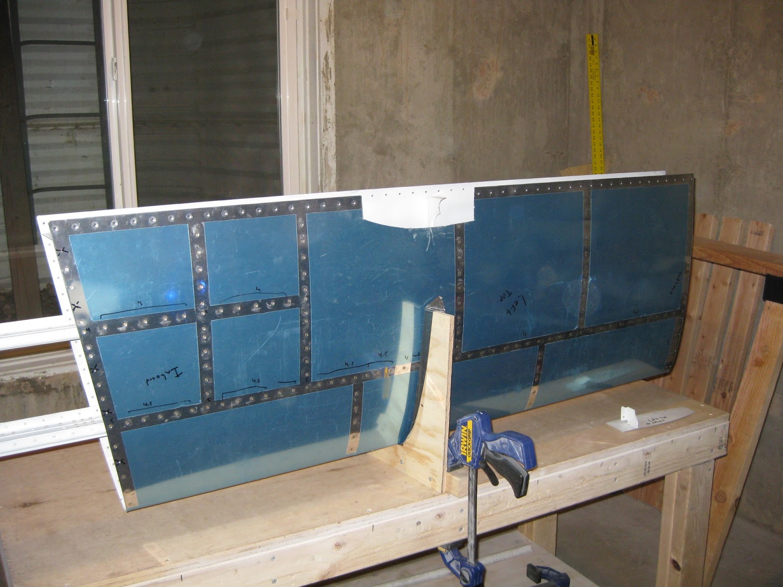
Dumfounded, I measured the hole spacing on my new rear spar with my caliper, afraid of another mis-punched set of holes.  Spacing was fine:  Exactly 1.125".  I then measured the hole spacing on the skin.  It too looked fine to me.  But clearly, there was a problem either on the spar or the skin (see first image below).  So, to ensure I had an accurate measurement, I seated unset rivets into the spar when it wasn't on the stab assembly.  Separately, I did the same on the skin when it didn't have the spar in it.  This way I could use the dimples in the AN426AD3 rivets as a good reference.  Turns out, the skin had two holes with spacings 0.02" too great!


Even though 0.02" isn't a big deal, two of them naturally add up to 0.04".  This creates a skewing of holes outboard.  Simply drilling these out up to a #30 wouldn't solve the problem because the dimples still wouldn't fit in the countersink for all holes outboard of the misalignment.


As another sanity check, a fellow -14 builder who completed a -6 and a tech counselor A&P who worked for United and the original Frontier and has also built several kit planes, to include a -12, both came to look at my stab to see if I was missing something.  They agreed with my assessment, though the tech counselor felt I could just drill out the holes to a #30 and use NAS1097 rivets in their place (my other tech counselor advised against this approach when the original problem surfaced).  I didn't believe that was feasible given that the dimples didn't seat into the countersinks due to the misalignment.  It would also greatly increase the risk of the dimples cracking due to the knife-edge cut from the drill.

I cut off the implicated pieces (spar and skin sections) from my original stab and sent them to Van's for examination (the image below may not be suitable for all audiences).  When they received my parts they told me the next day that they couldn't find anything wrong with them (click here for an update on this outcome).  They stated that they found the spacing to be correct and that my spar countersinks were a bit under-countersunk.  They felt the latter may account for the less than optimal layup.  To their credit, they involved several relevant people internally to investigate possibilities including looking at their CAD files, checking inventory parts and even cleco'd up a few stab mock-ups.  They took this issue very seriously even though I'm the only -14 builder to report this issue with these parts to-date.  They sent me images showing the skin portion riveted to the spar portion.  For sure, the mis-punched skin and spar portions would fit fine, but this is because they were both mis-punched in such a way that the two misaligned parts align fairly well.  However, that skin won't fit properly on a good spar and neither will the bad spar portions fit good skins (I wonder if they've misunderstood the problem).


Their assessment perplexes me.  Obviously I disagree with their conclusion, as precise measurements illustrate incorrect hole spacings on my original rear spar and left top skin and the fact that the new spar fit in 3 of the four places the old one didn't.  Even slightly deep countersinks couldn't account for these observations.  At this point it's moot.  Despite the different conclusions that we've both reached, they've agreed to send me parts to rebuild a new stab.  That represents a significant cost on their part and that is highly appreciated on my part.

My original horizontal stab was probably one of the best pieces in the build:  Only one very minor dent on the skin that no one would have known was there.  I hope that can be repeated on stab #2.

I guess I now have some hangar art in the form of a grounded, handicapped horizontal stabilizer.

Update 13-Dec-14:  Another builder ran into the same problem as I, posting on VAF.  In his communications with Van's, they found that the spar is too large to chuck up once, so it has to be rechucked in the machine at about the locus of where mine and his mis-punches occurred.  In case other builders run into the same issue, Van's is manufacturing several rear stab spars without holes punched so builders can simply match-drill the unpunched spar to their skins directly.  I'm not sure why a simple replacement, properly punched, spar isn't the better approach.  But at least Van's identified the problem and I'm no longer some lone builder relegated to Crazy Town.