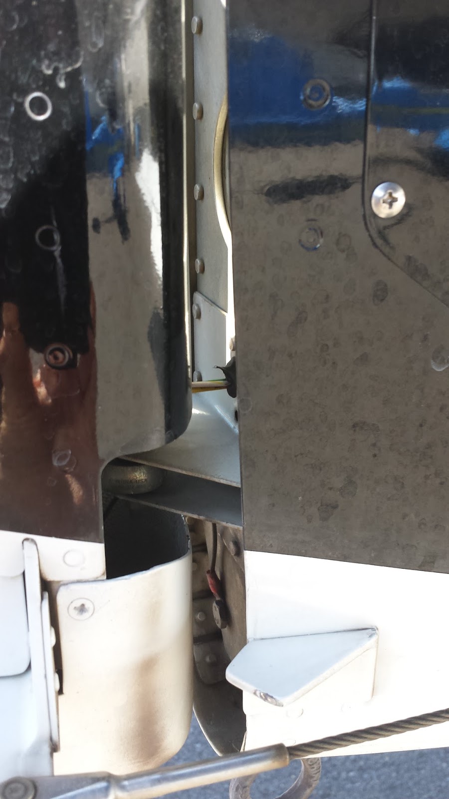
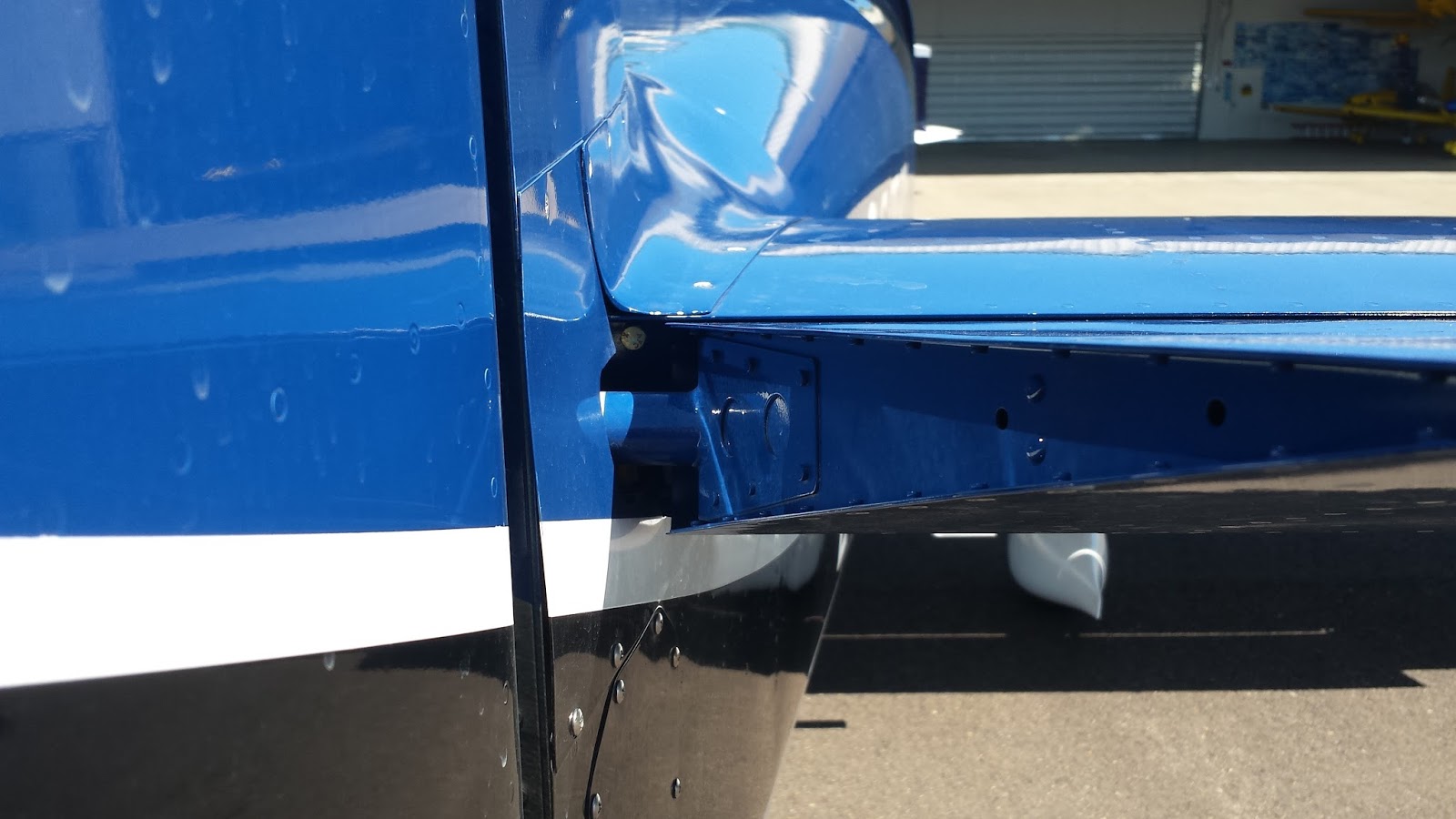
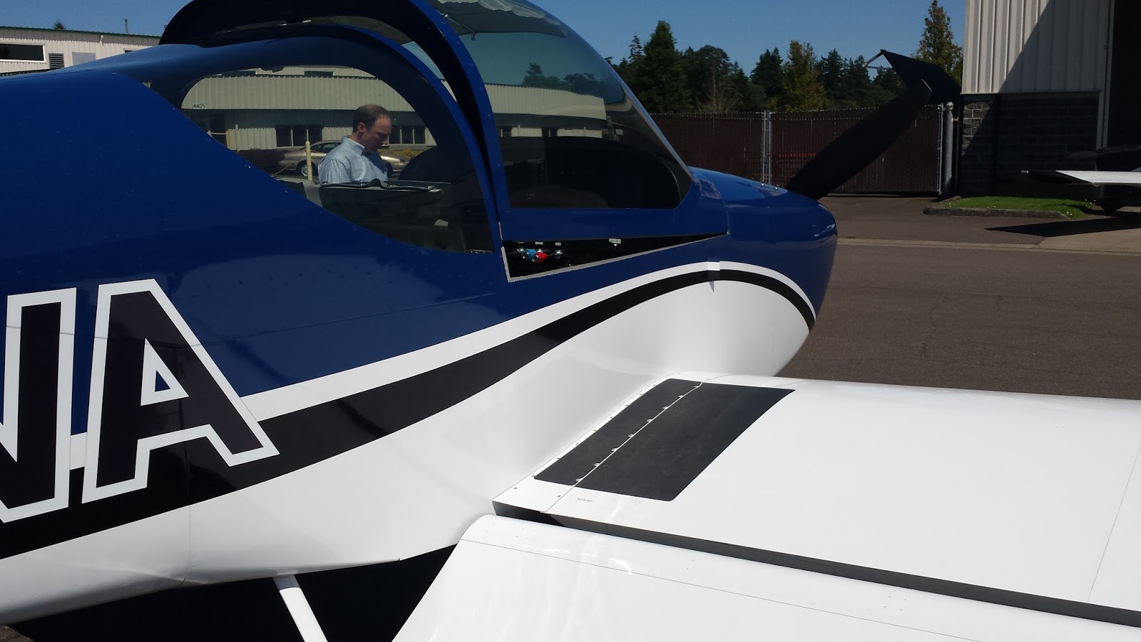
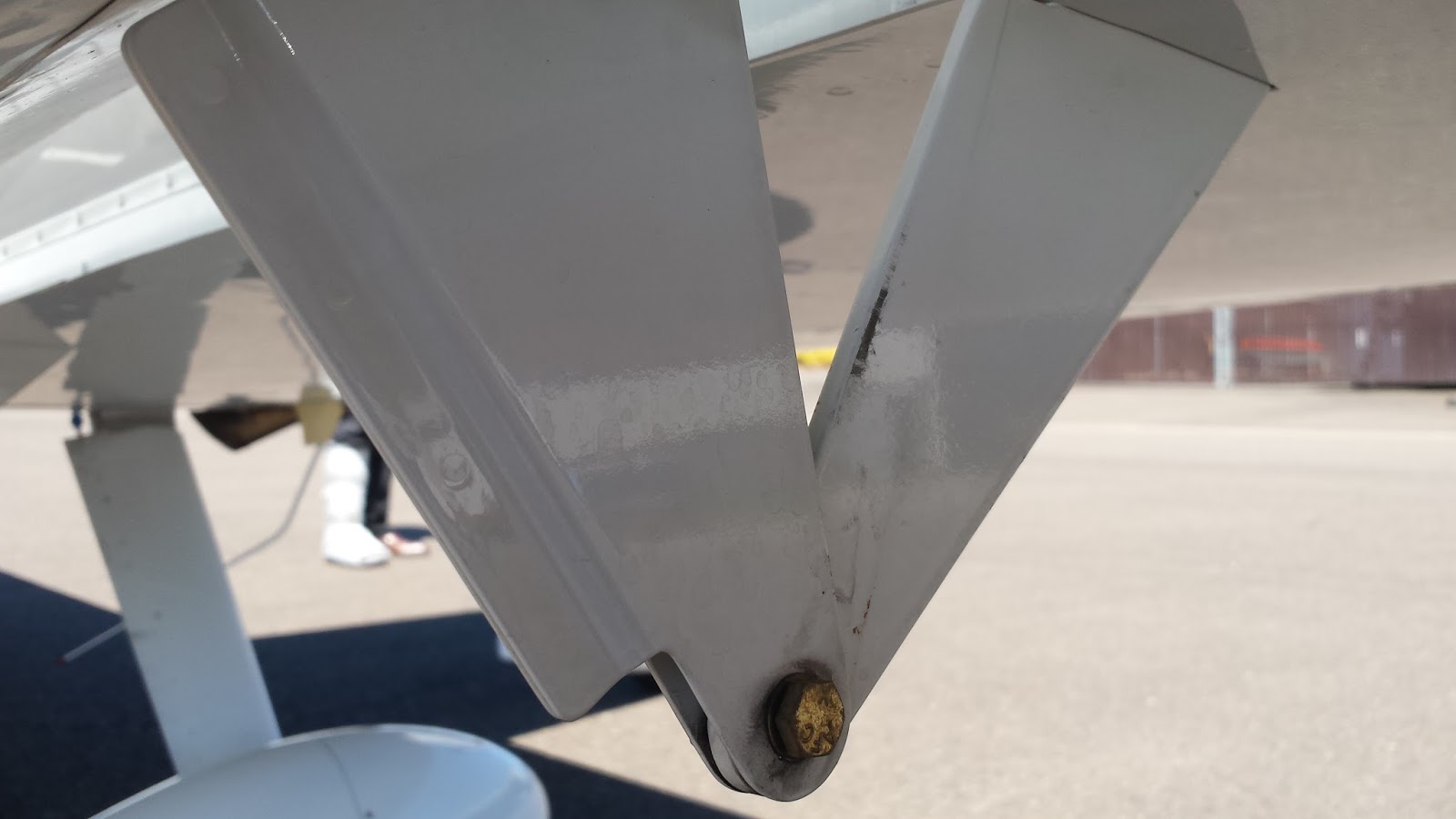
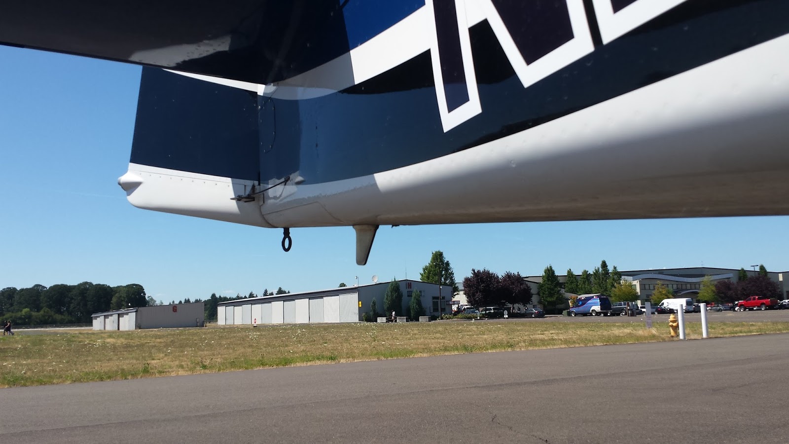
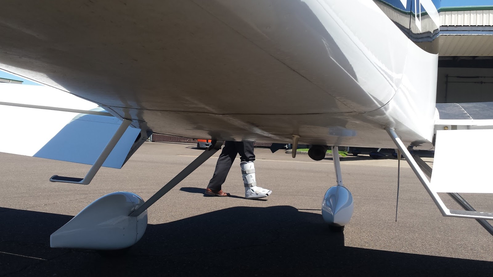
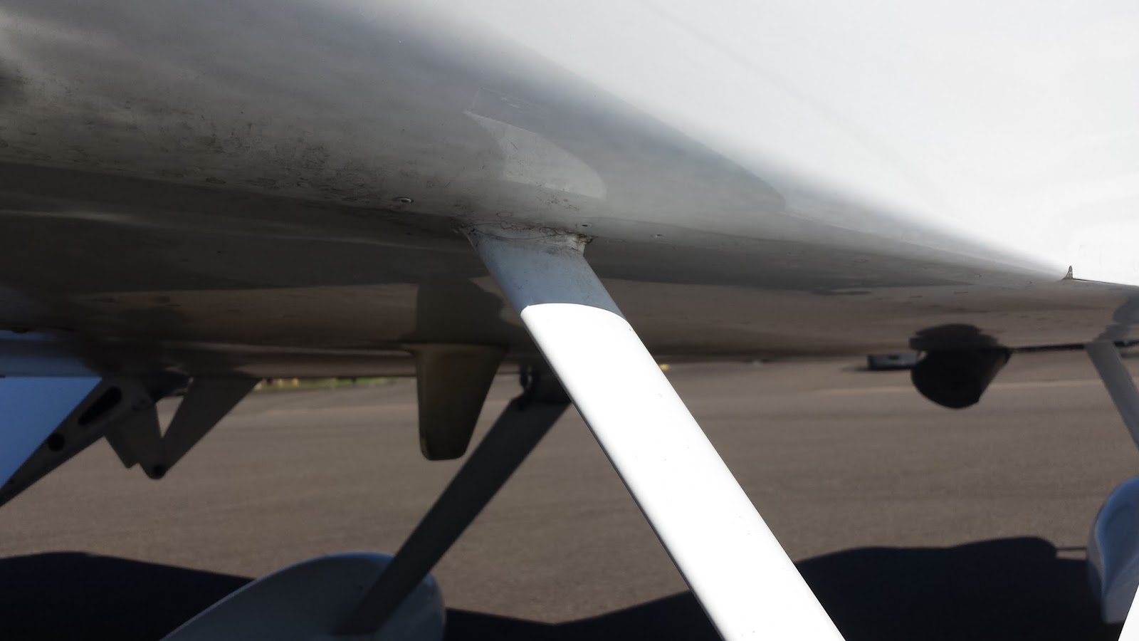
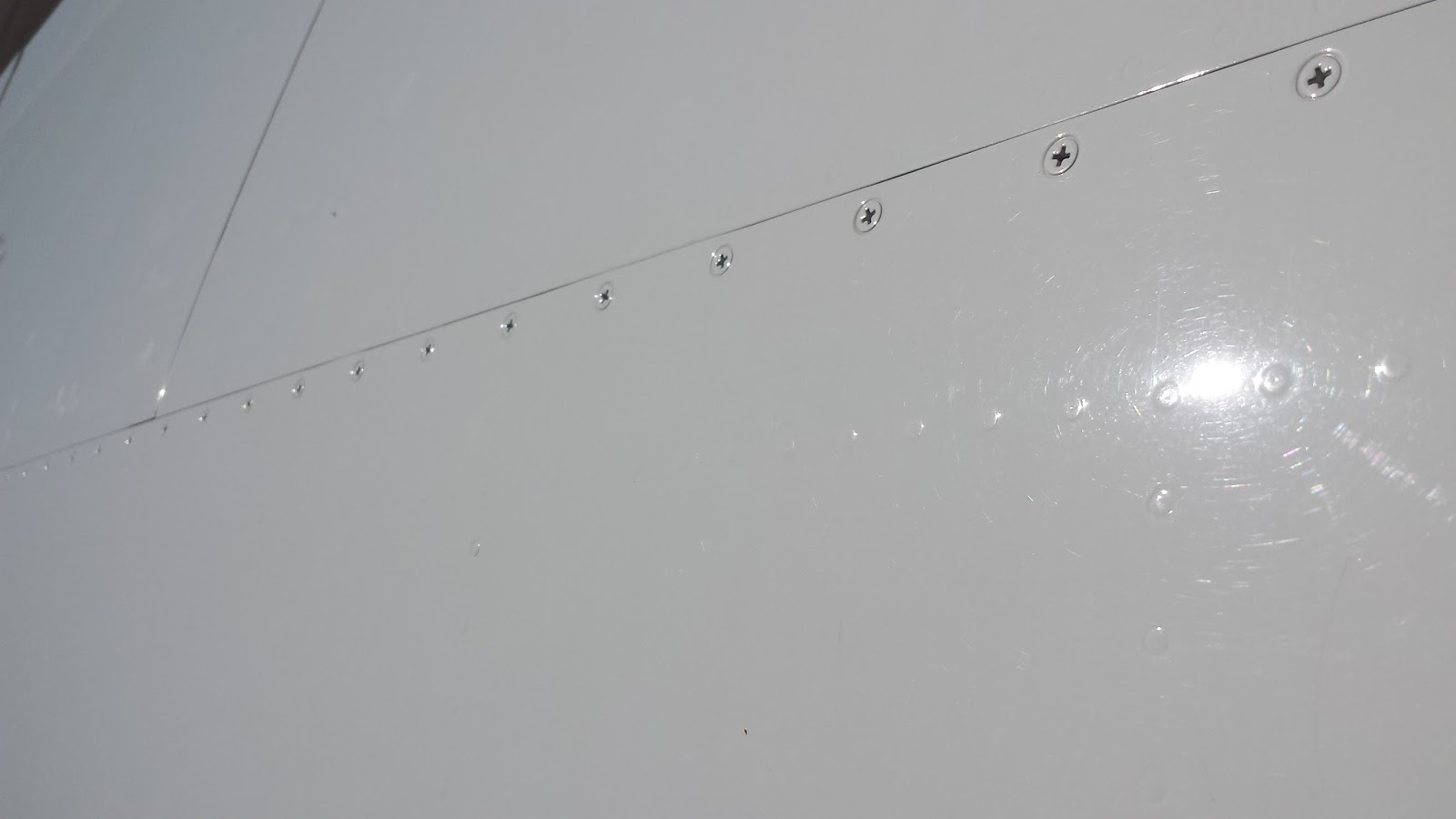
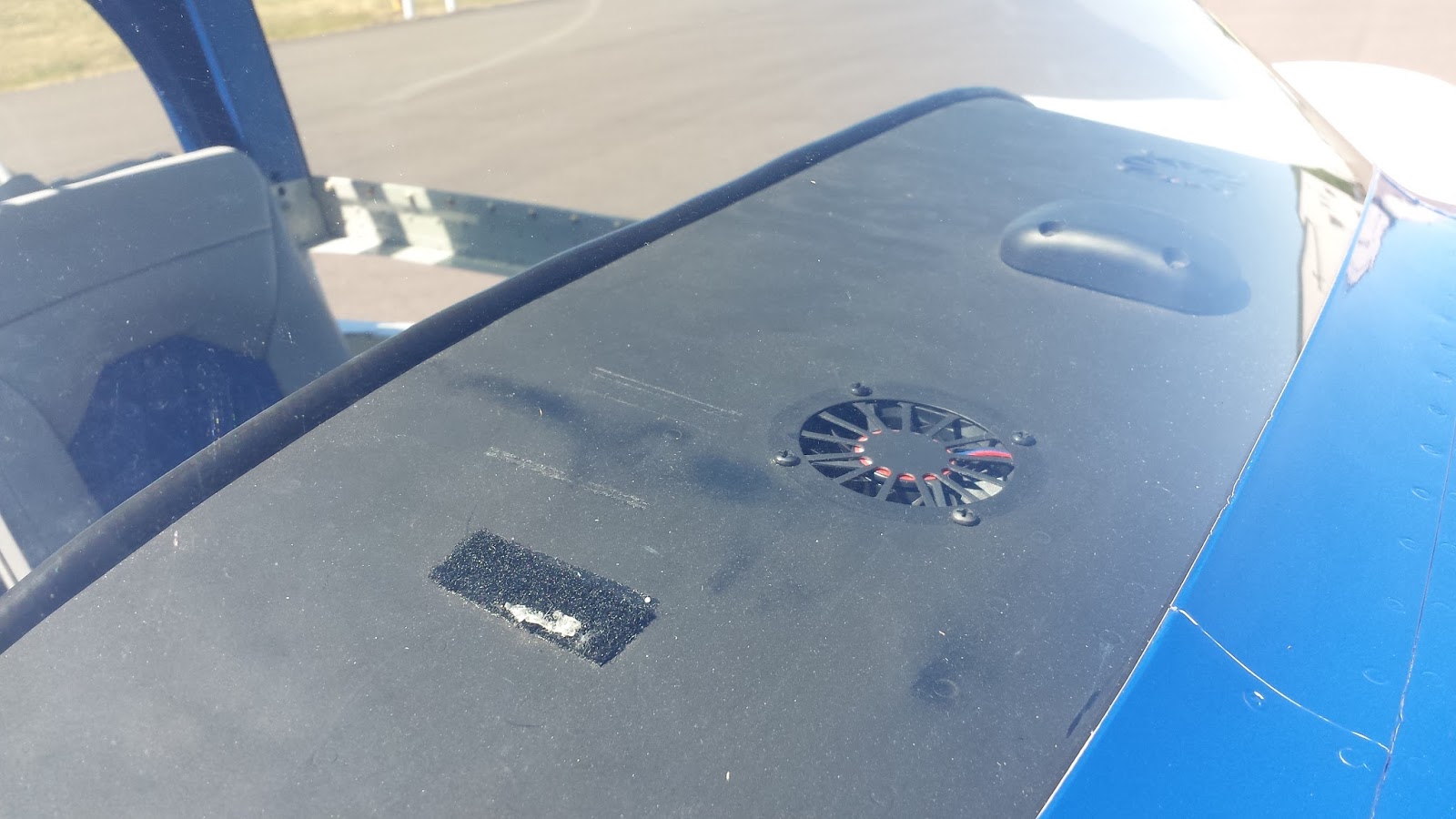
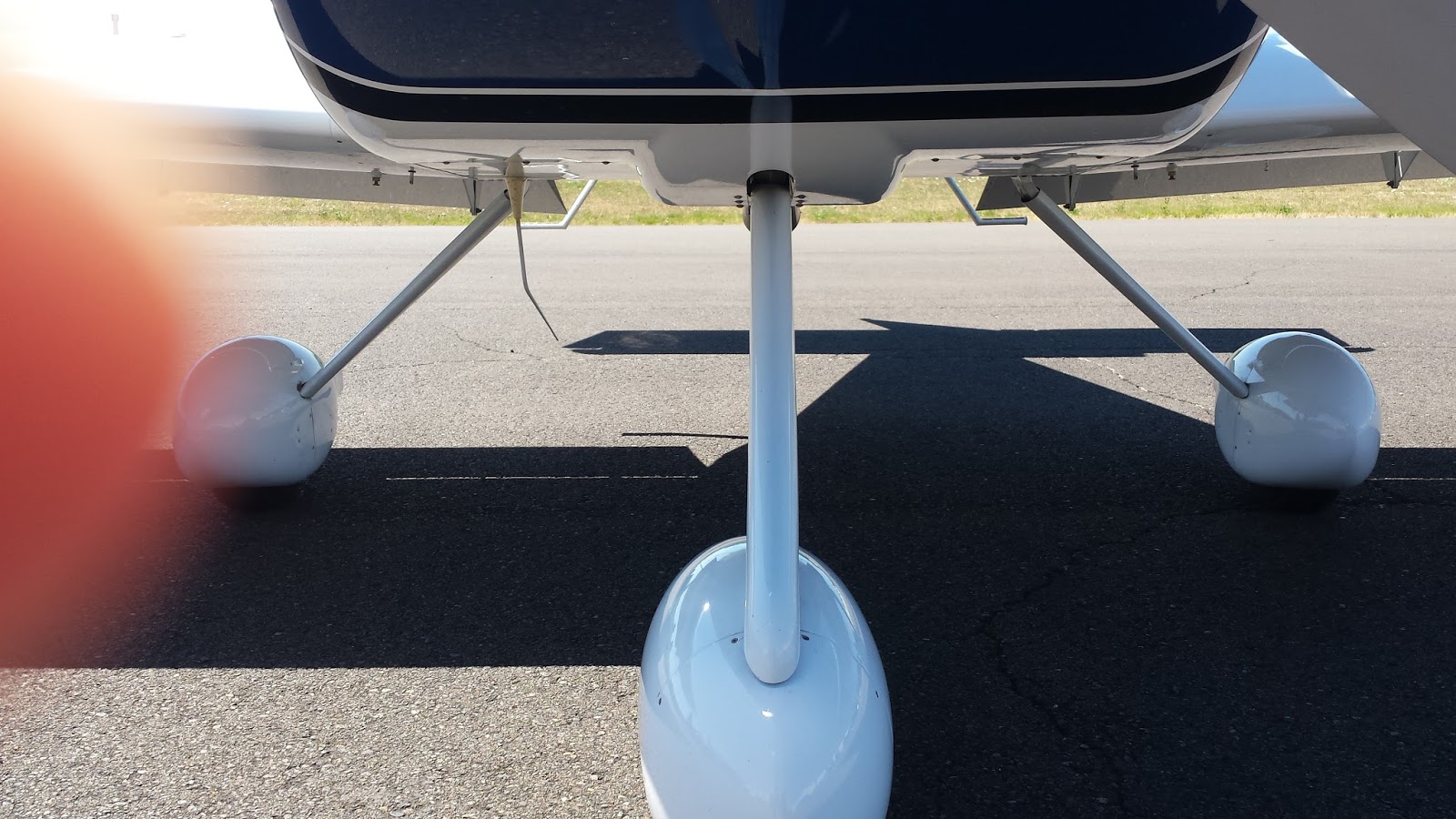
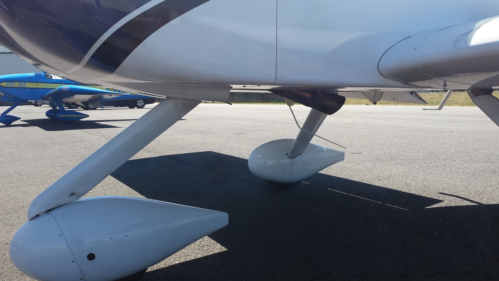
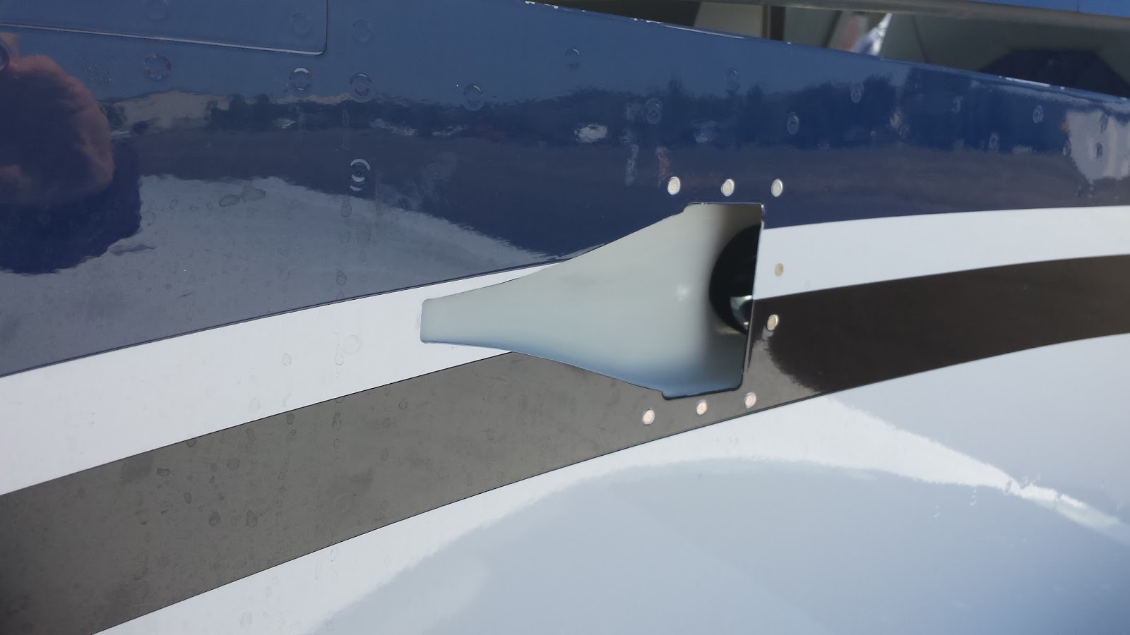
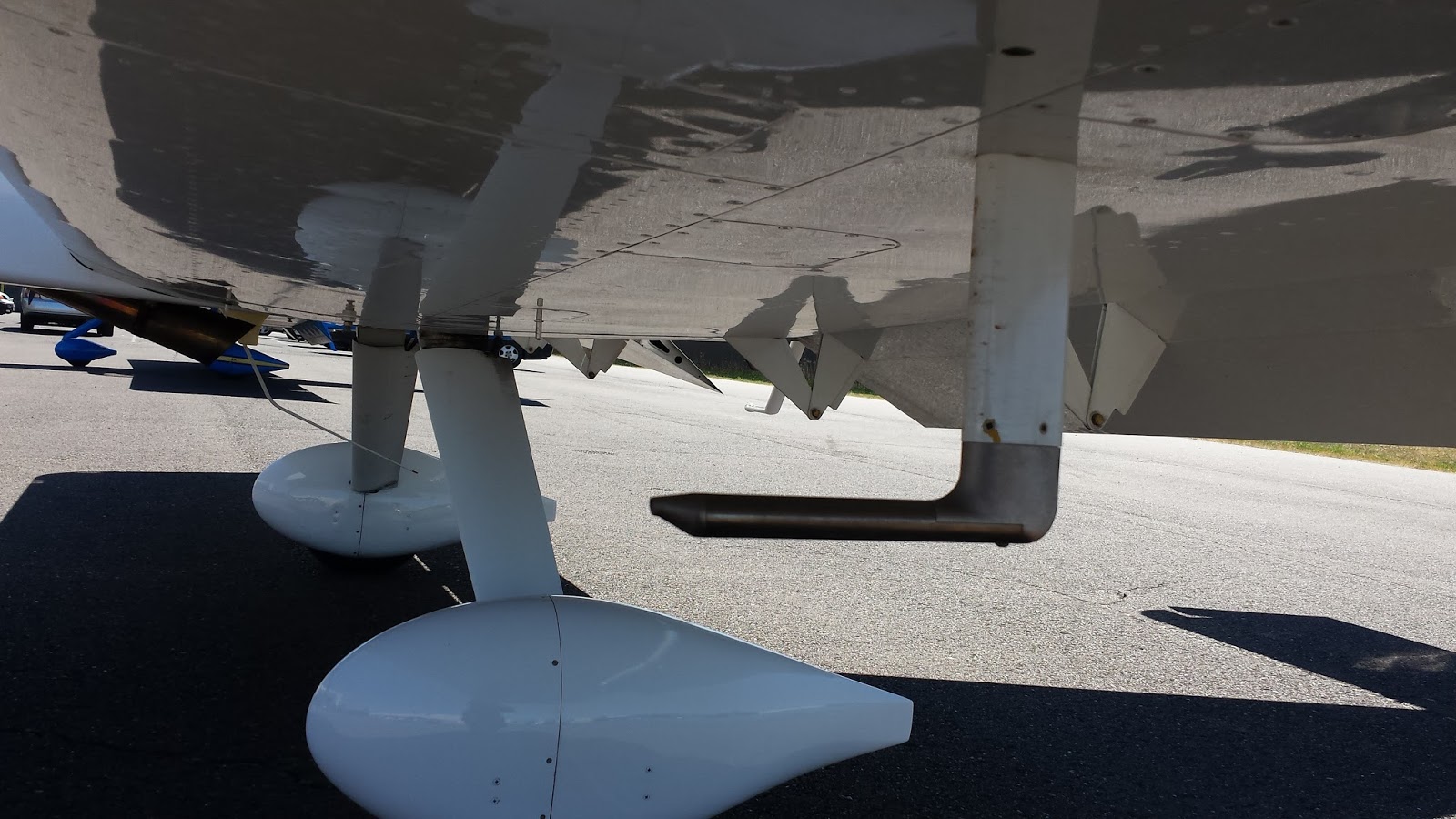
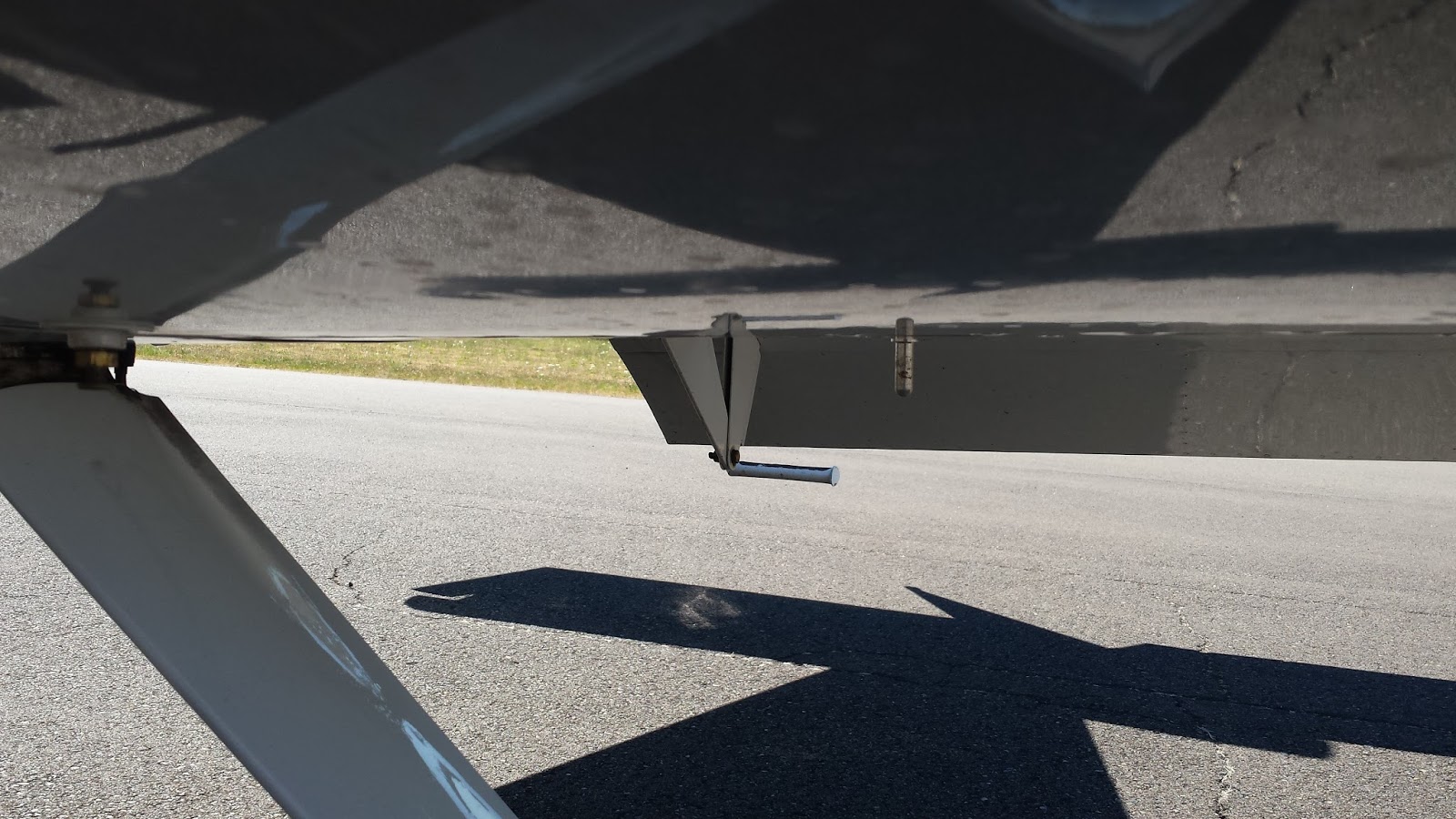
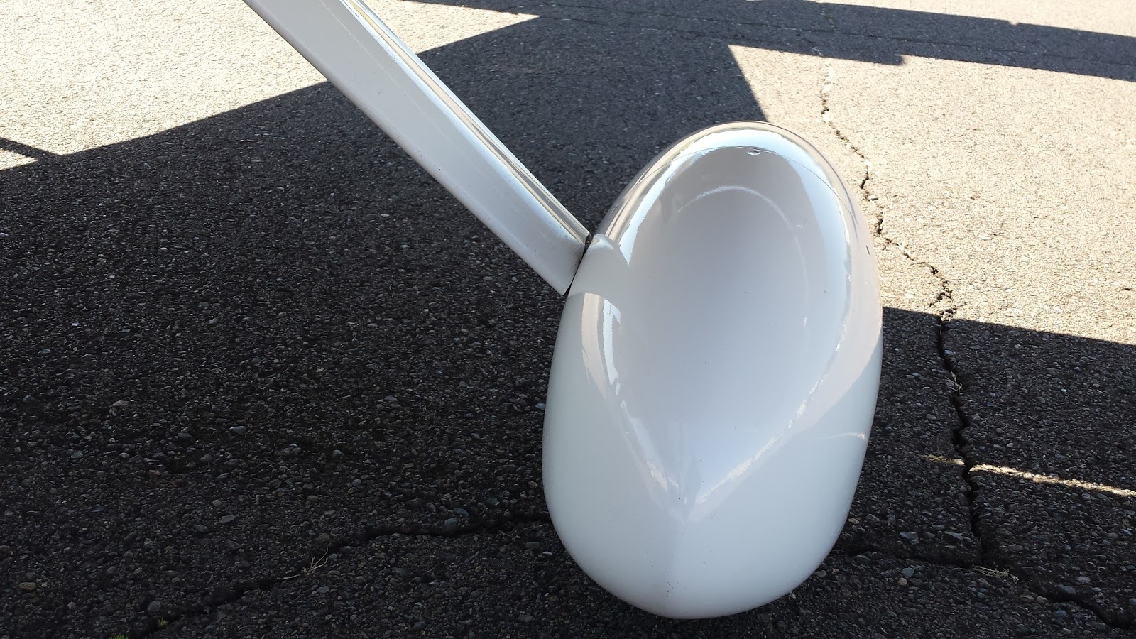
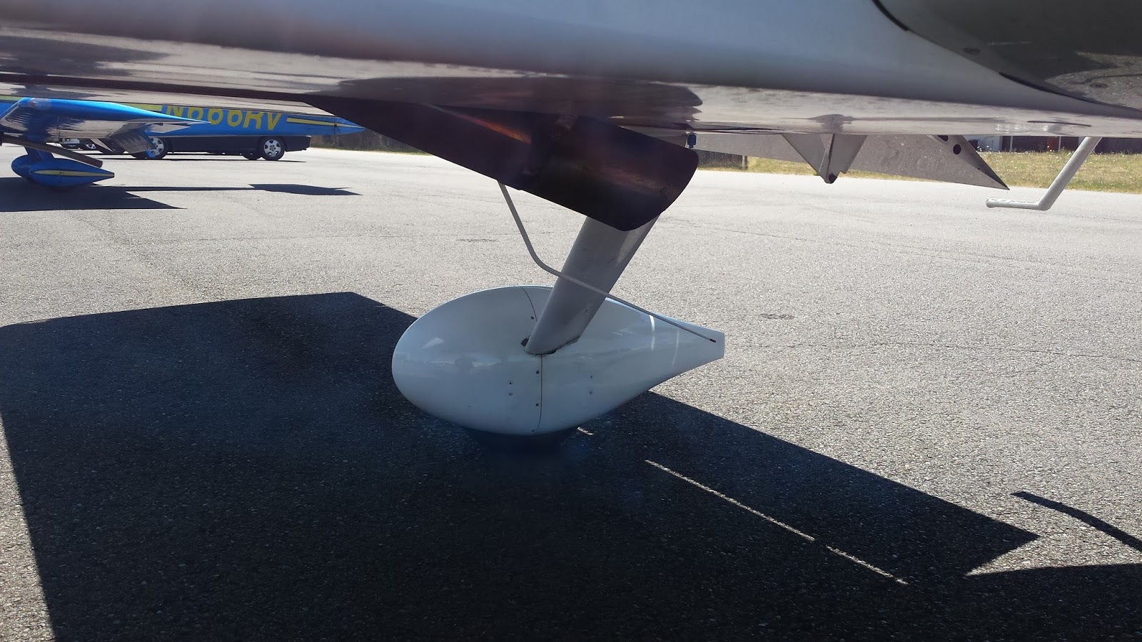
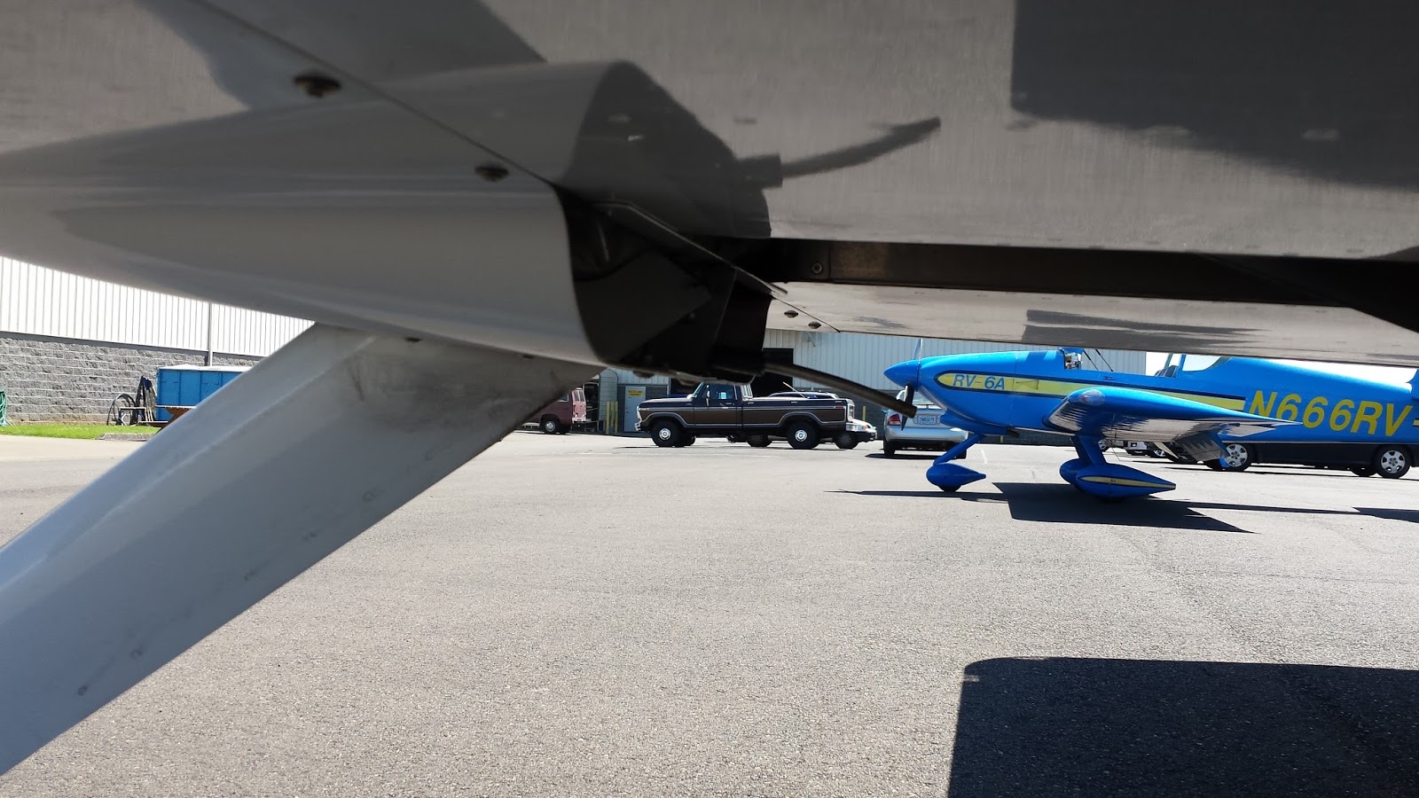
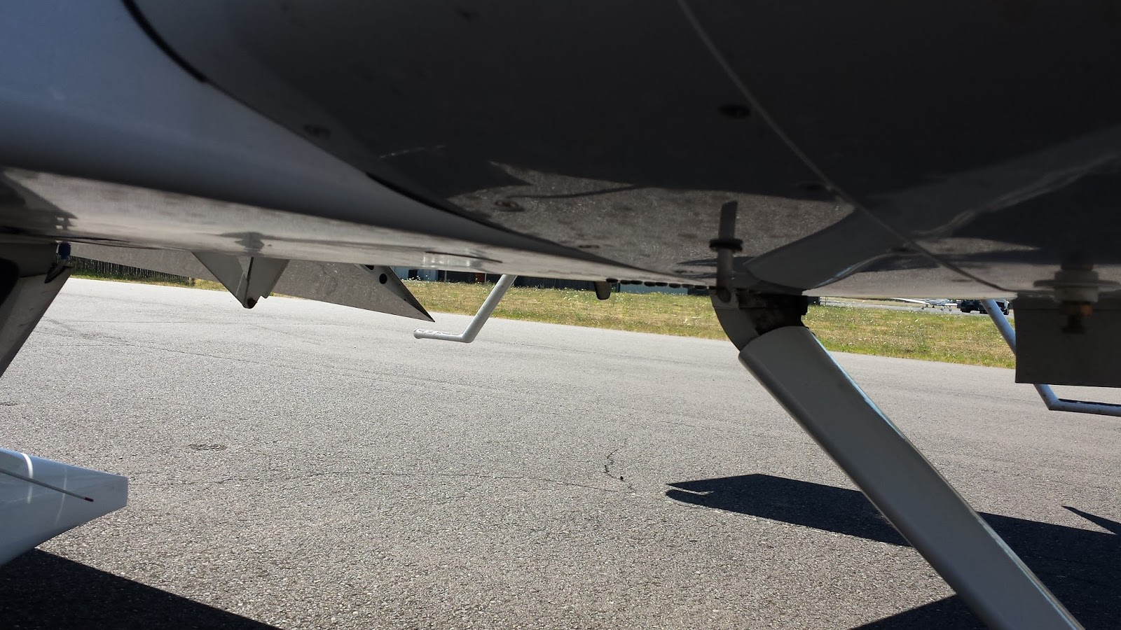
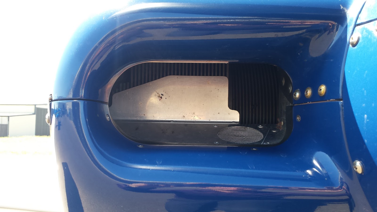
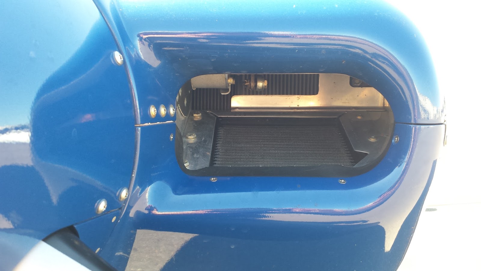
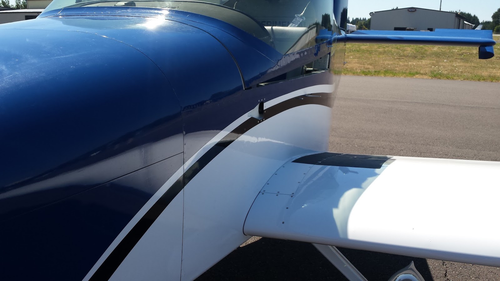
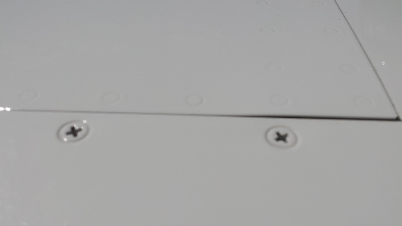
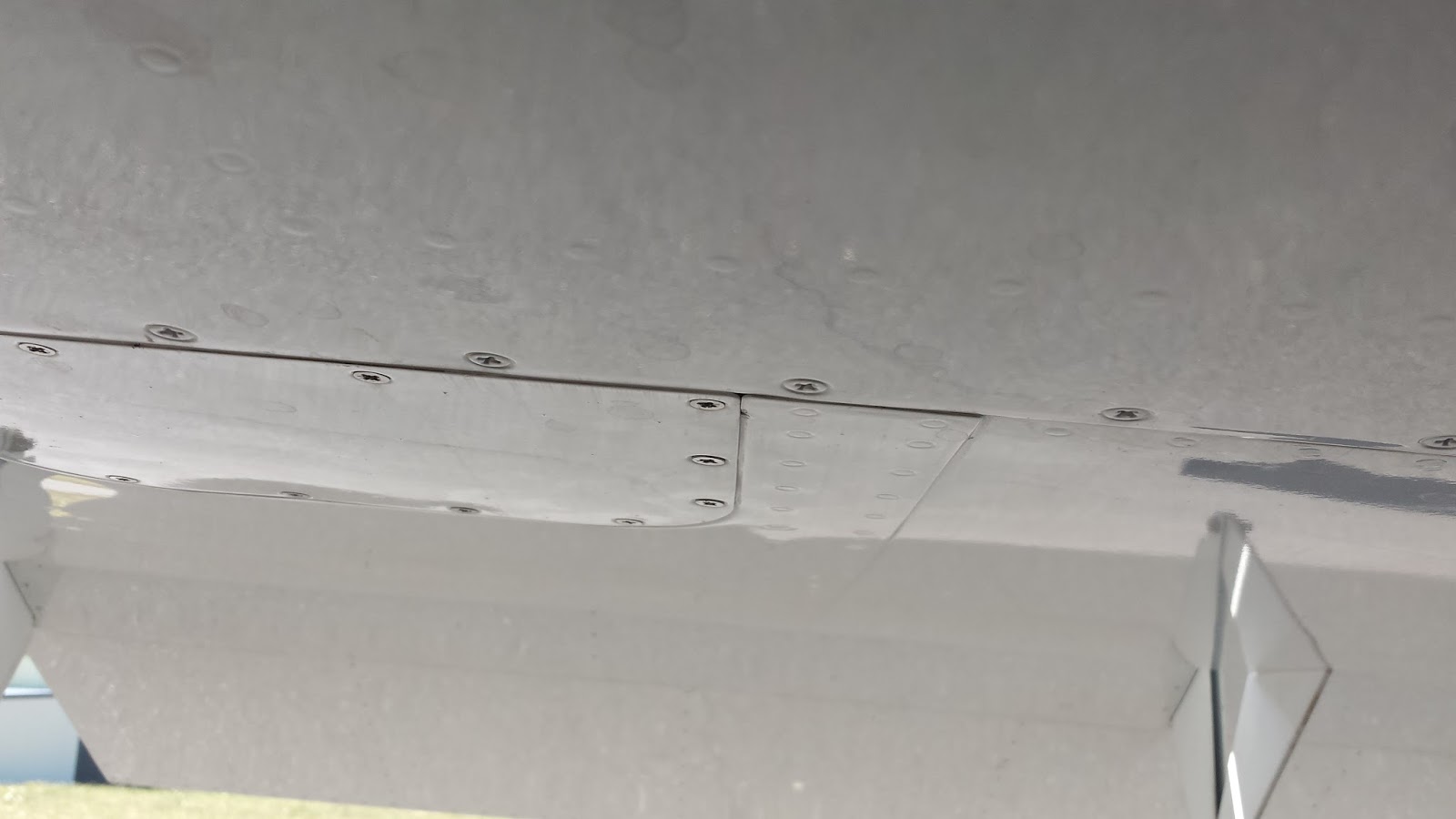
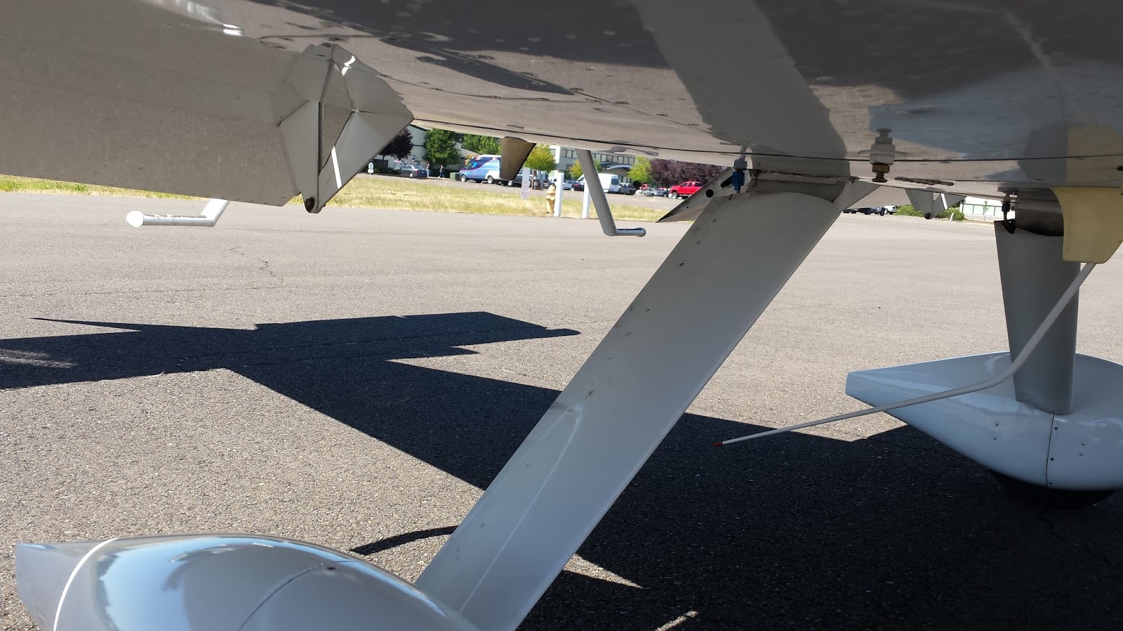
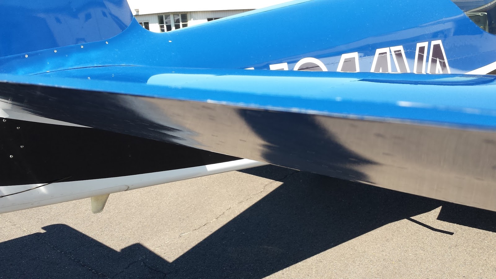
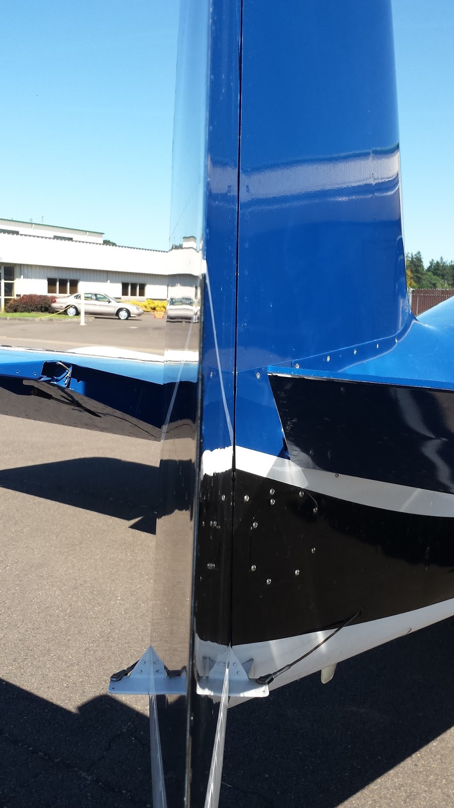
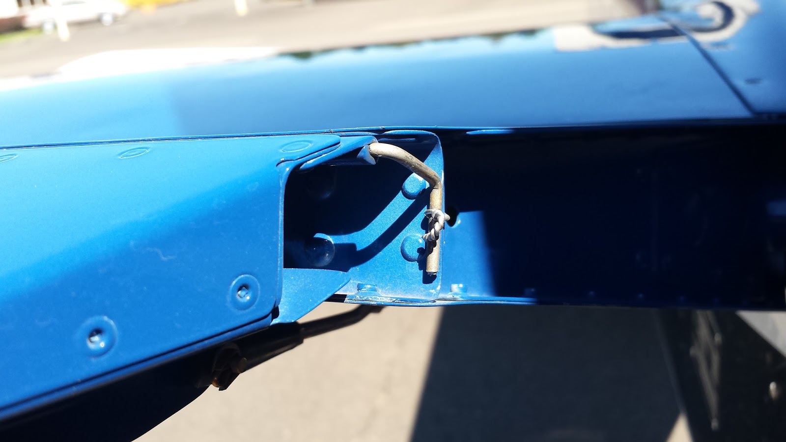
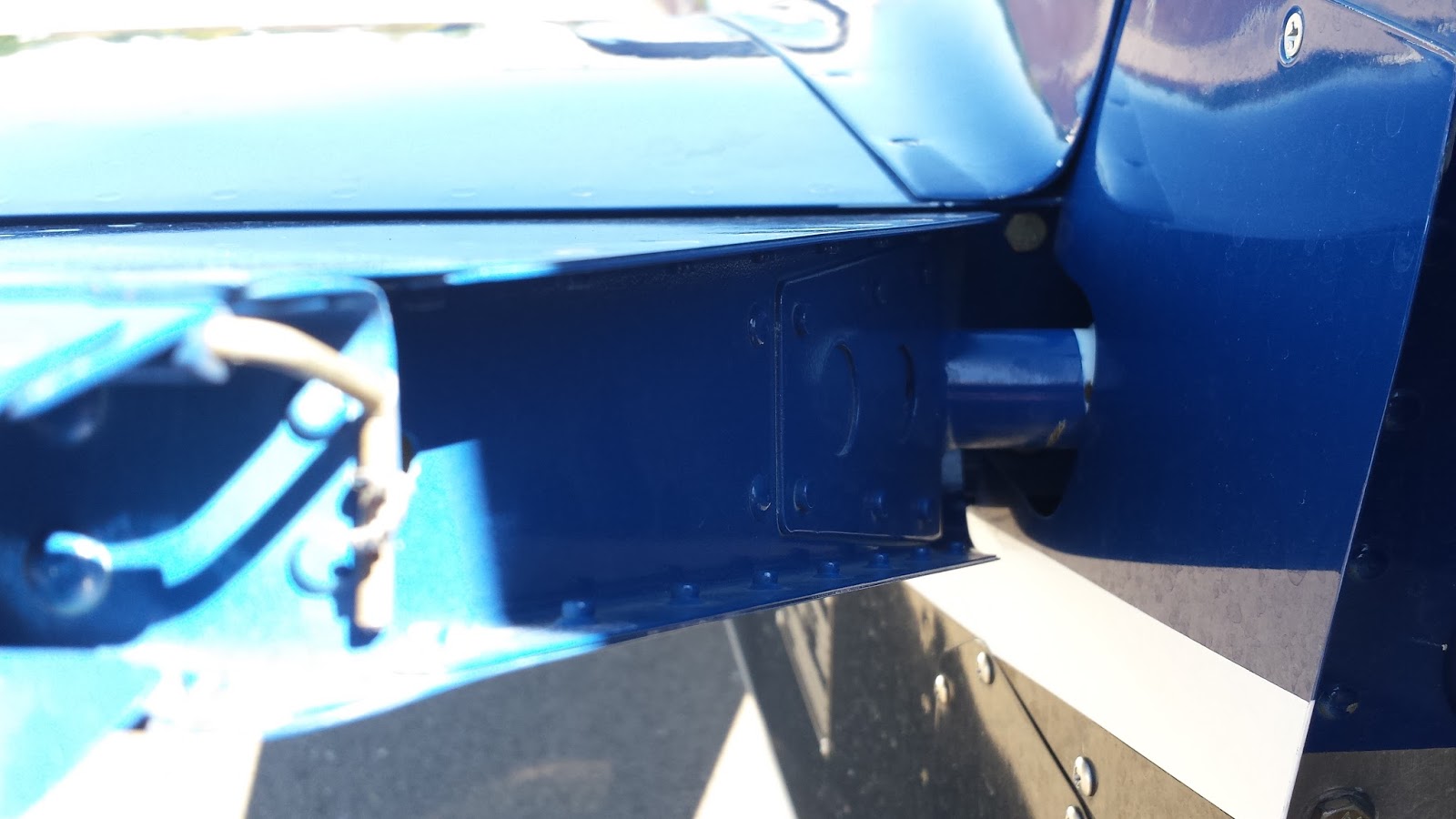
I had a visit from my tech counselor today. Wanted to get his thoughts on a couple of things. No major findings.
16 August 2014
11 August 2014
Empennage: Elevators. Rolled leading edges.
After much reading of various RV blogs and VAF, I decided on the following method, as described in this VAF post. Another example of a similar process is found here. Getting this right is important, otherwise it could lead to cracking.
I obtained some 3/4" ID conduit which was 15/16" OD. I drilled similarly sized holes in three blocks of wood, leaving the holes much closer to one end than the other (to accommodate the elevator spar) for the conduit to slip in, then cut one side of the blocks just tangent to the holes. This netted me three of the following.
I obtained some 3/4" ID conduit which was 15/16" OD. I drilled similarly sized holes in three blocks of wood, leaving the holes much closer to one end than the other (to accommodate the elevator spar) for the conduit to slip in, then cut one side of the blocks just tangent to the holes. This netted me three of the following.
I then laid a sliced-open trash bag on the work table so the elevator could slide along the table with lower friction. The picture below also shows the conduit slid into the clamped-down wood blocks.
Next I applied duct tape (does anyone actually use that stuff on...ducts?) to one side of the elevator skin. Half of the width of the tape was stuck to the skin, leaving the other half for the conduit.
I slid the conduit into the three blocks. Then I placed the elevator on the bench with the flayed trash bag and nested the conduit against the spar temporarily to ensure the blocks could fit in the two spaces for the horizontal stab hinges and the other block could fit adjacent to the inboard skin edge. I then wrapped the remaining width of tape around the conduit.
Then I inserted a pipe wrench fitting into the conduit (which held up for two rolling events, after which I just used a channel lock) and twisted the assembly. The elevator was drawn in as the skin was rolled.
What I ended up with was the image below. The roll was not close enough to the spar so the skins were nowhere near close to each other. Had I continued rolling, the middle edges would have been curled inwards too far. So this caused me to do a lot of manual bending, trying to avoid creasing the skins at the spar. On the other elevator, I tried placing the conduit further in towards the spar prior to taping things down, but the outcome was the same. If I were to do this again, I'd use a 1.5" OD pipe.
Eventually I coaxed the skins to get their holes to line up, but with more "preloading" then I prefer. An apt characterization of this process might be "less than fun".
And although the top skins overlap the bottom skins without gaps (due to both the "edge break" I imposed on the tops skins and the fact that the top skins curl inwards), the bottom skins don't quite sit flush against the top skins (because the bottom skins also curl inwards). See below for illustration of that outcome.
Currently the elevators sit with their leading edge skins cleco'd up. I'm debating on what further to do, if anything, before riveting. That pre-loading to get the skins to align isn't appealing.
07 August 2014
Empennage/Lighting: Suntail rudder light purchased.
Picked up AeroLEDs SunTail anti-collision strobe and position light from Van's when I visited the home base.
Fun Stuff: I made it to the mother ship! Lots of photos!
A lengthy post which departs from the build anthology...
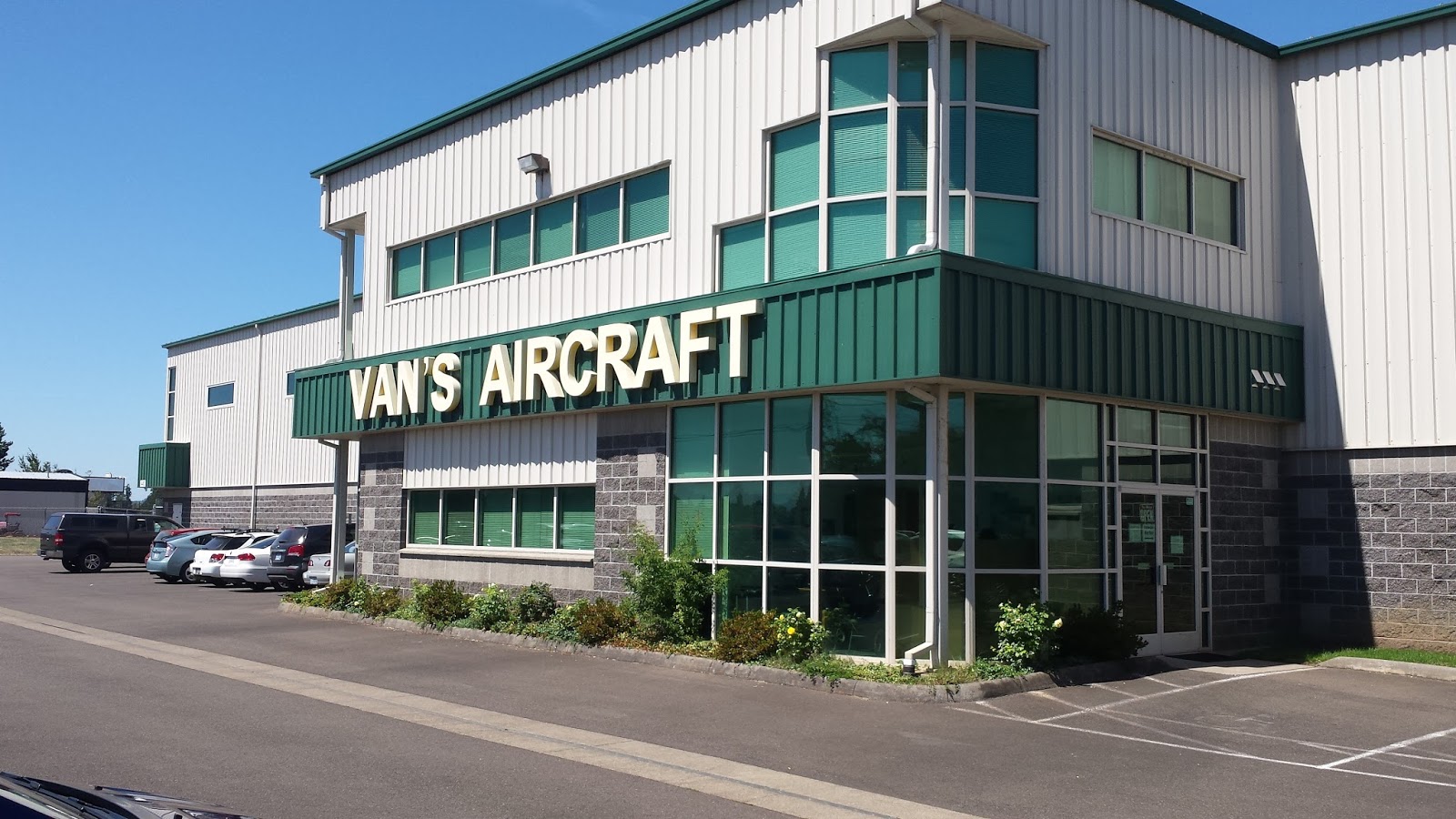
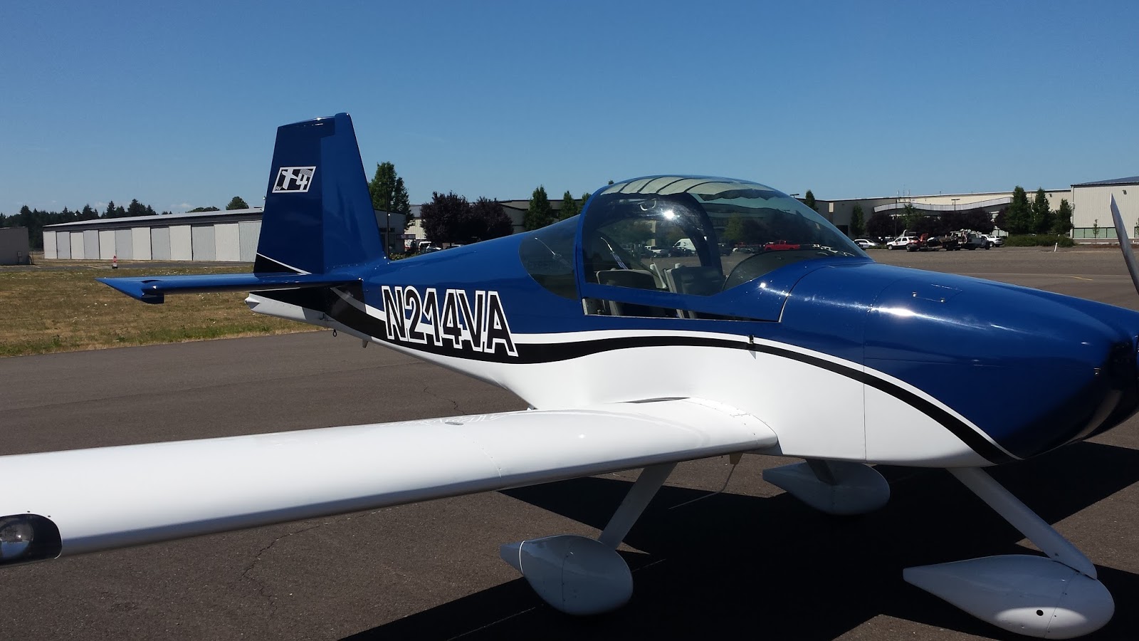
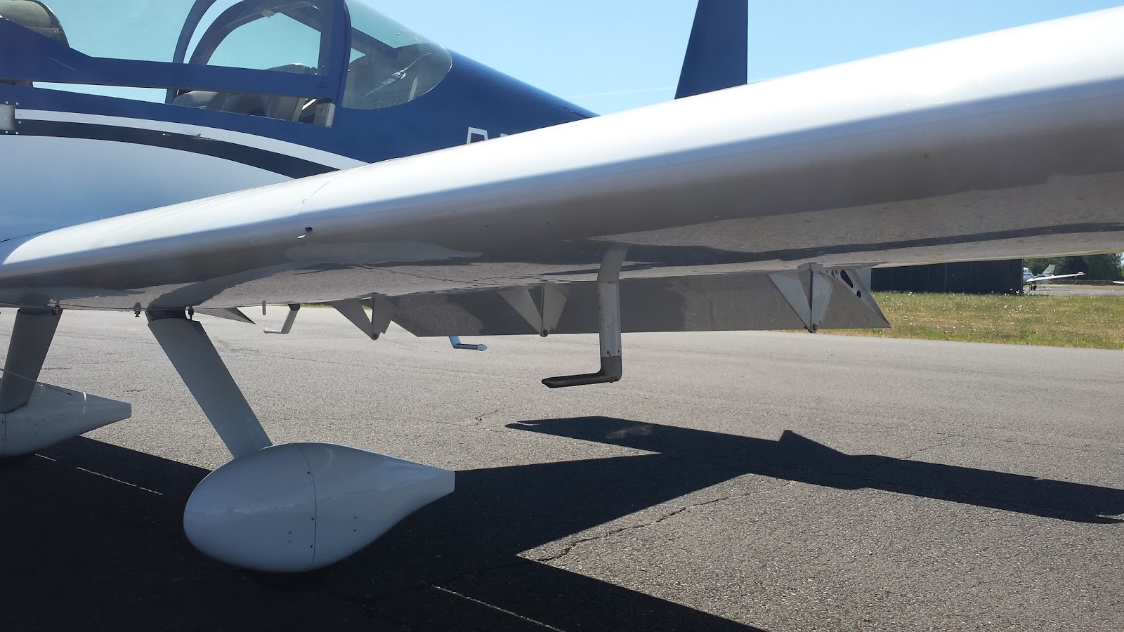
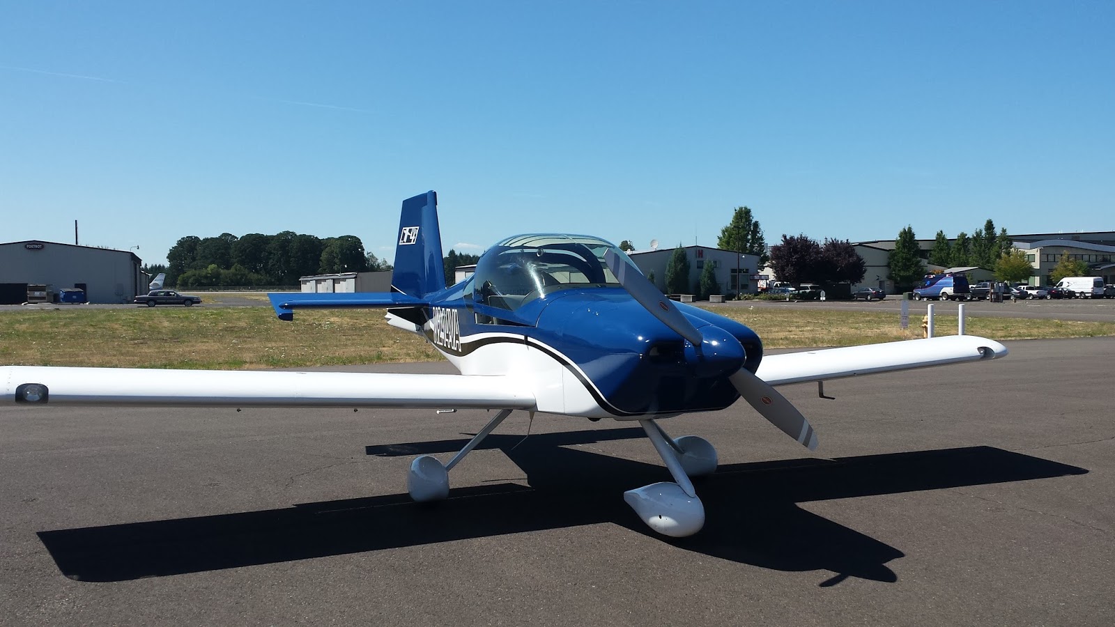
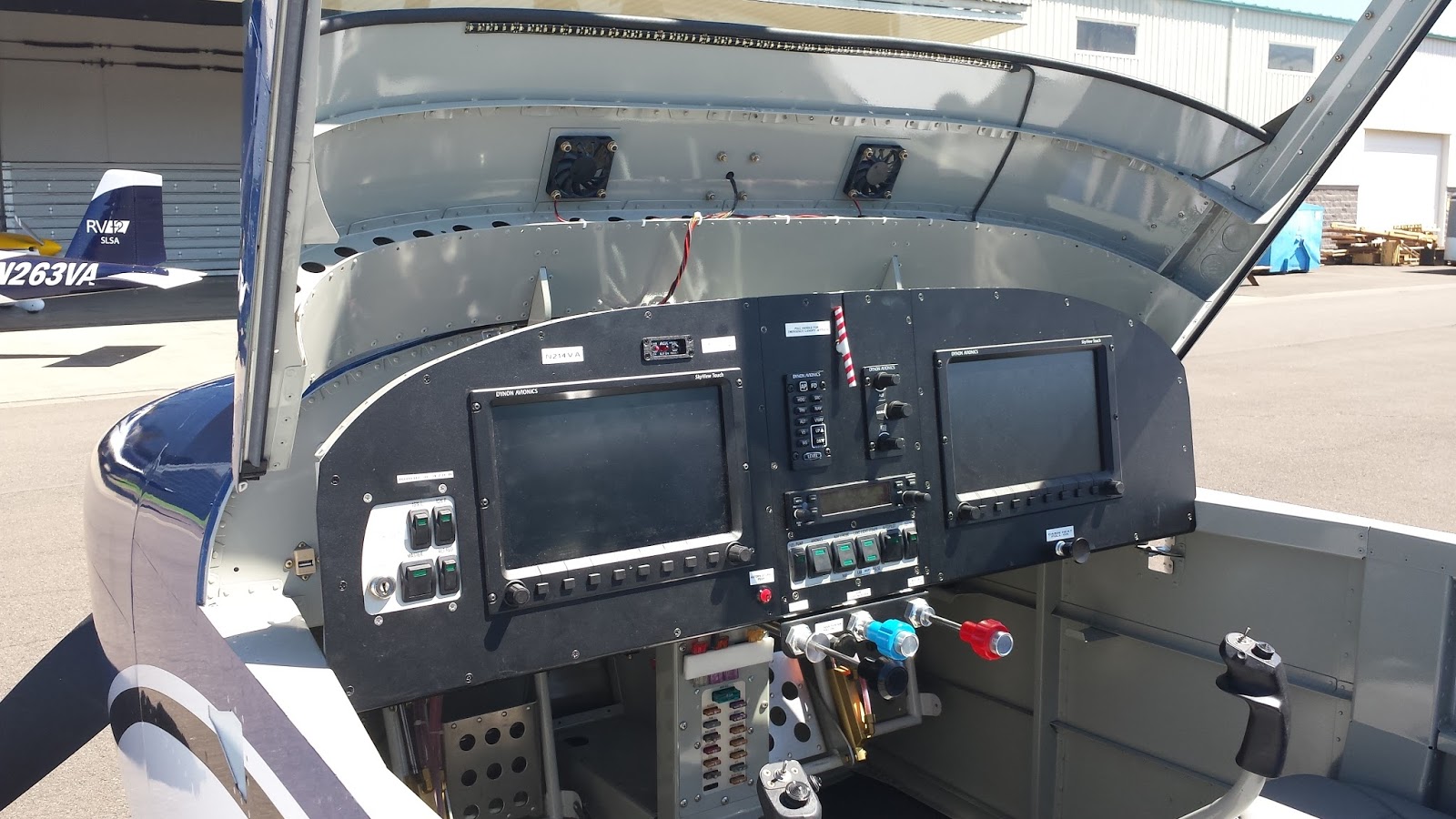
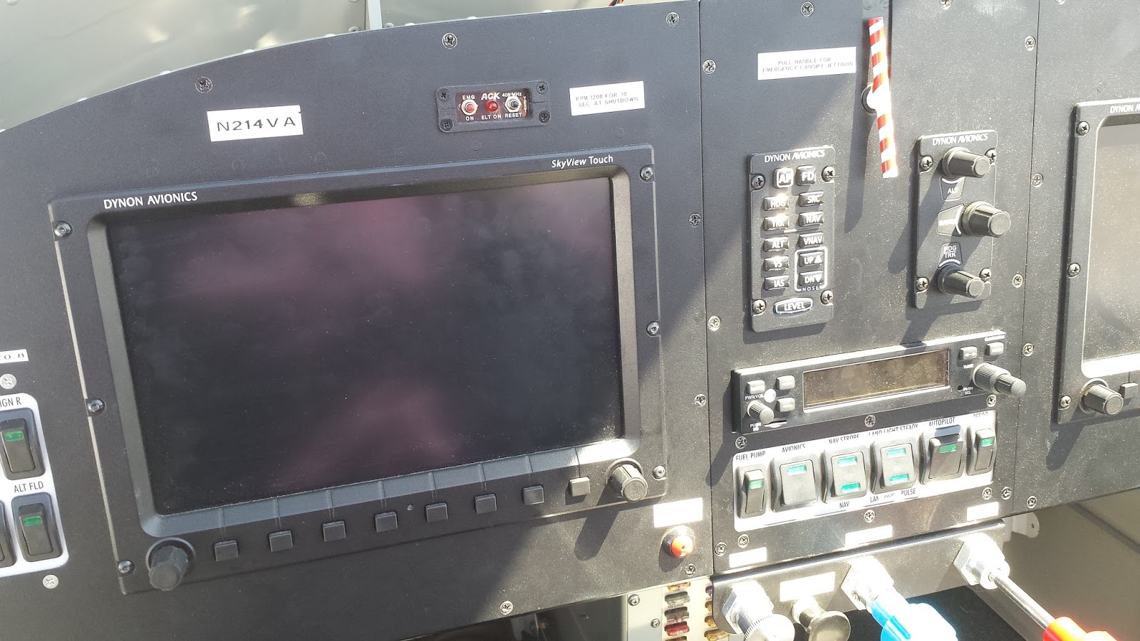
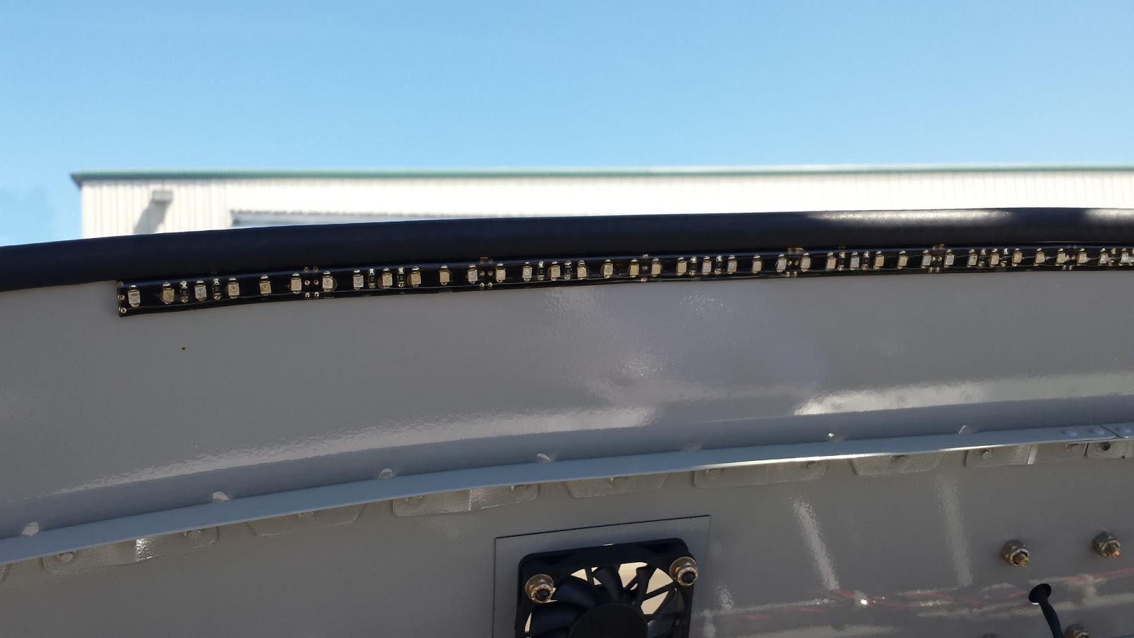
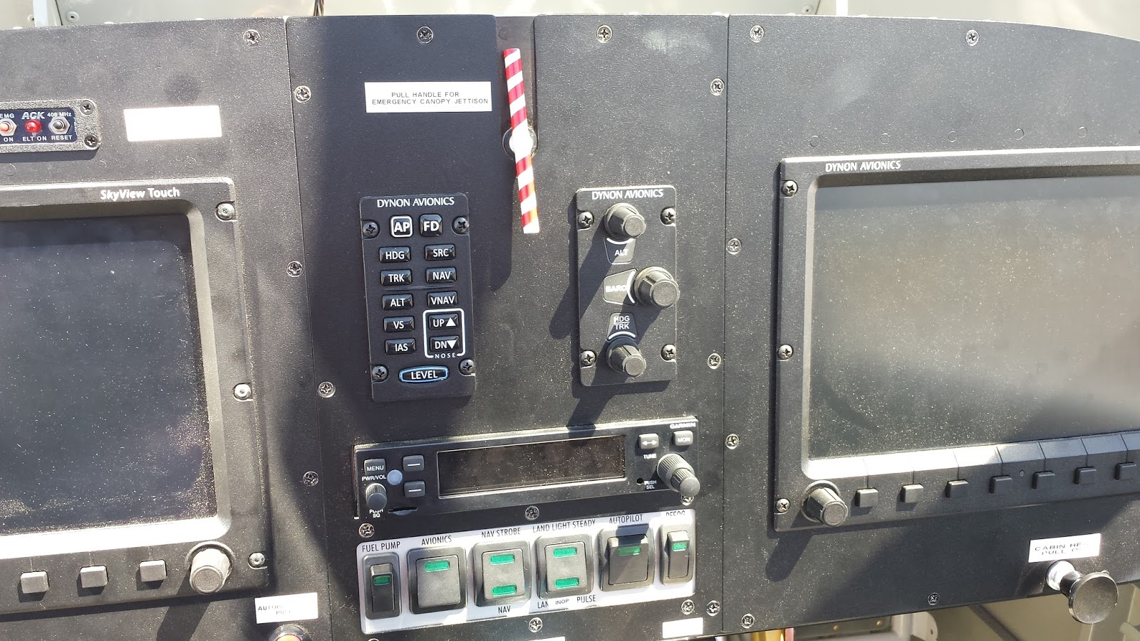
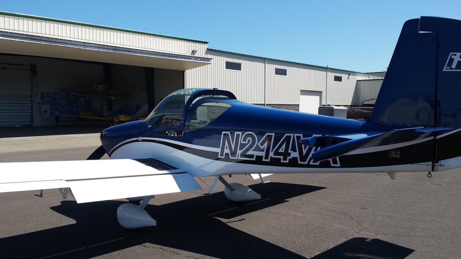
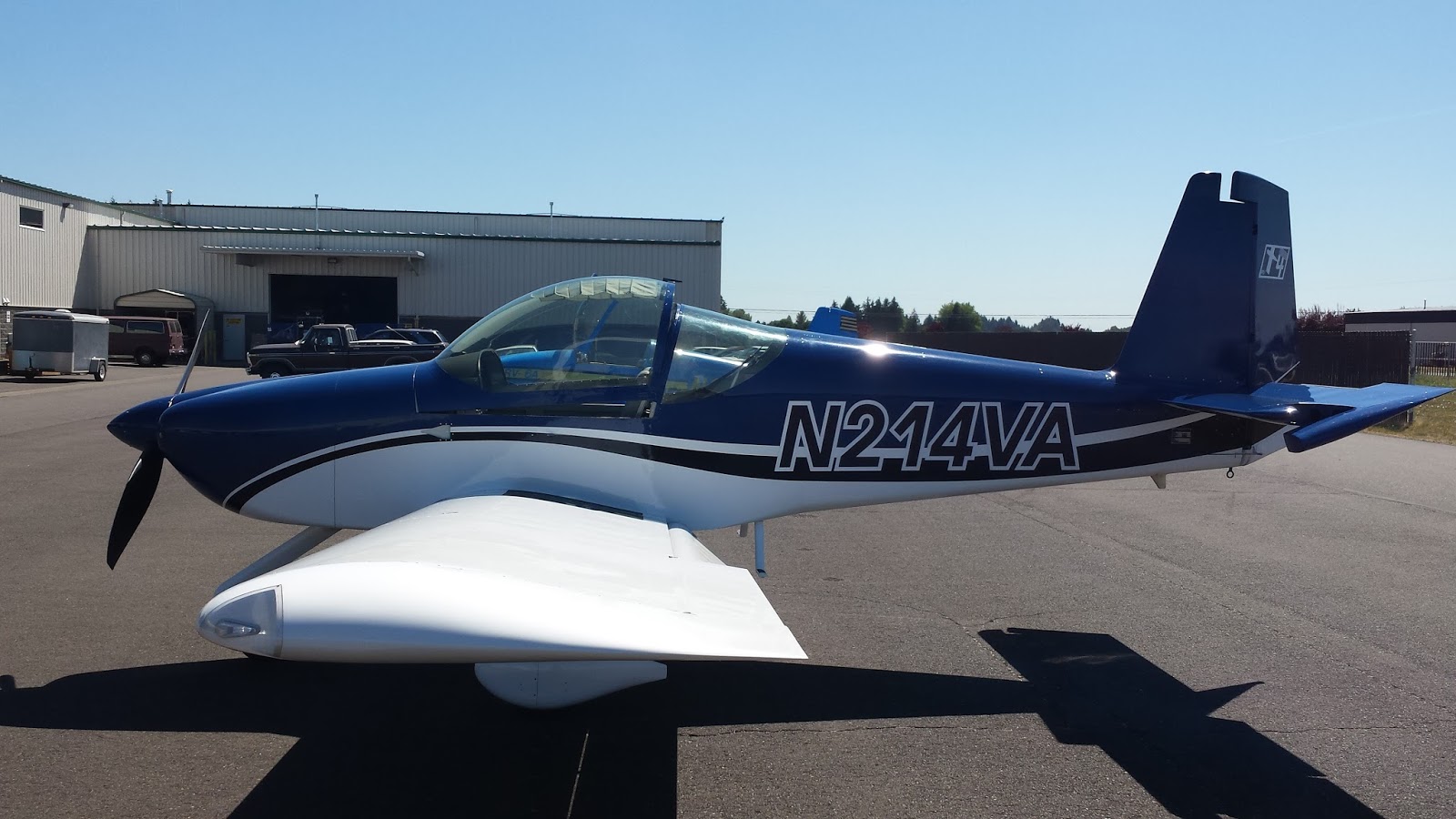
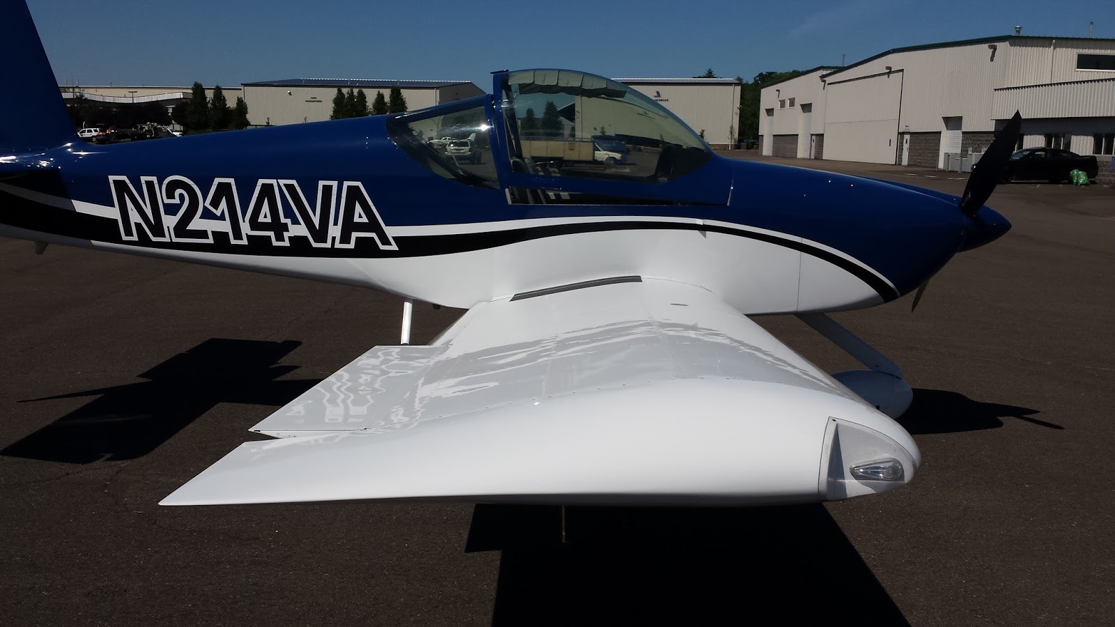
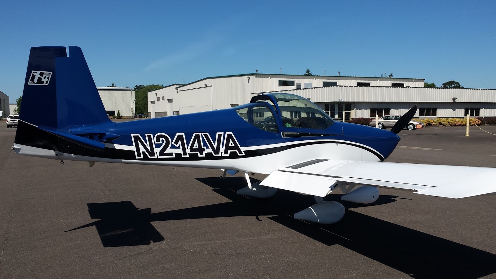
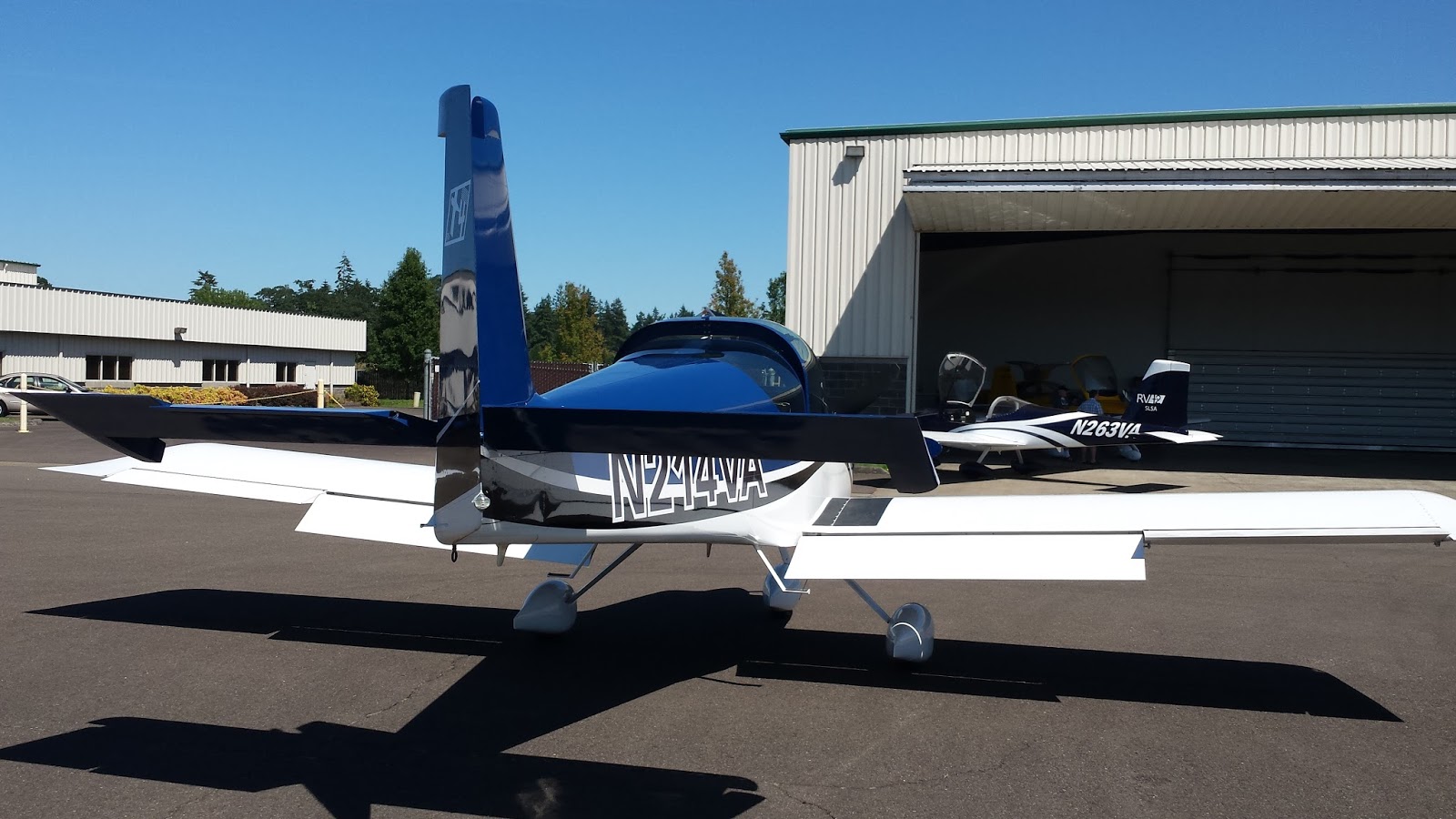
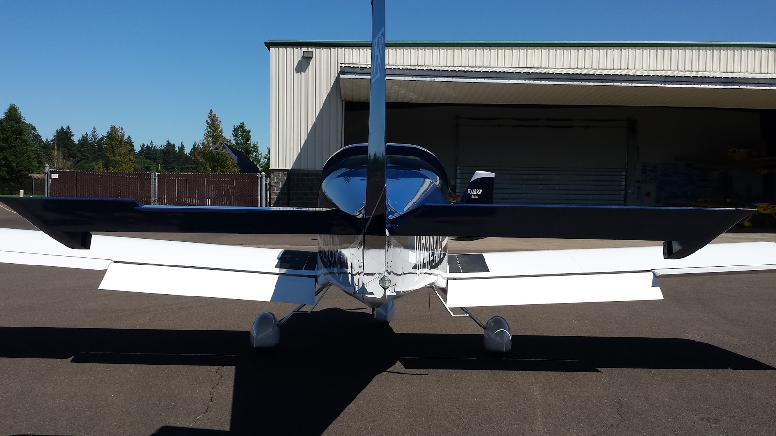
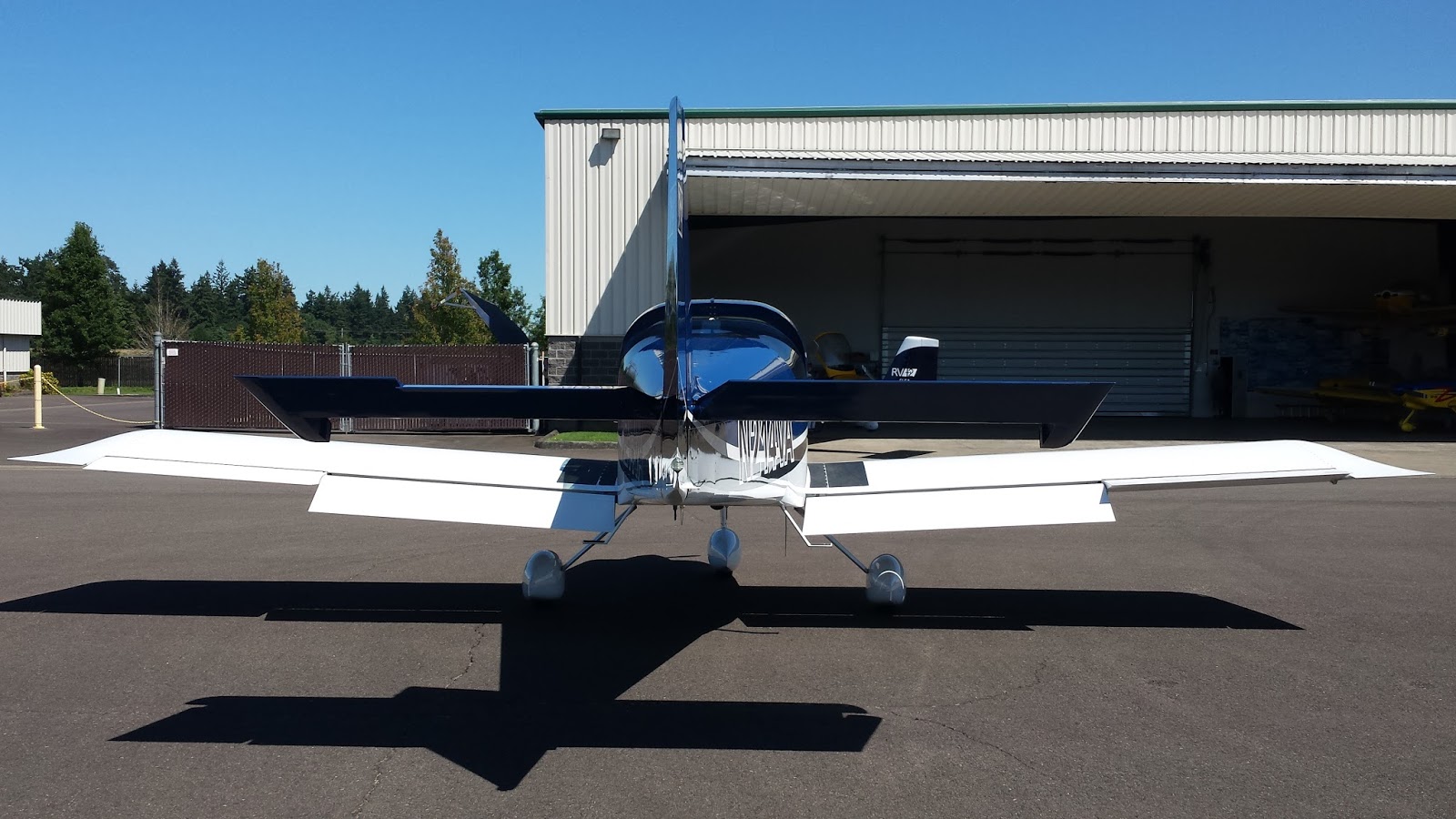
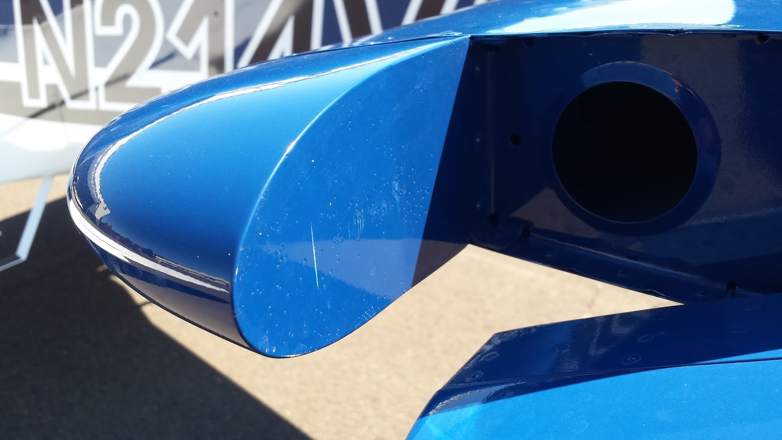
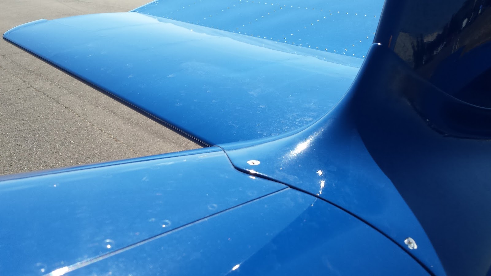
I happened to be in Portland Thursday with a few hours free, so why not go to Aurora, OR, KUAO? I got a nice tour from Ken S. and enjoyed spending time with the venerated N214VA. It was my first time seeing and sitting in the airplane I'm building. Also got to chat briefly with Scott R. and meet Fedosia. Very nice people.
I happened to be in Portland Thursday with a few hours free, so why not go to Aurora, OR, KUAO? I got a nice tour from Ken S. and enjoyed spending time with the venerated N214VA. It was my first time seeing and sitting in the airplane I'm building. Also got to chat briefly with Scott R. and meet Fedosia. Very nice people.
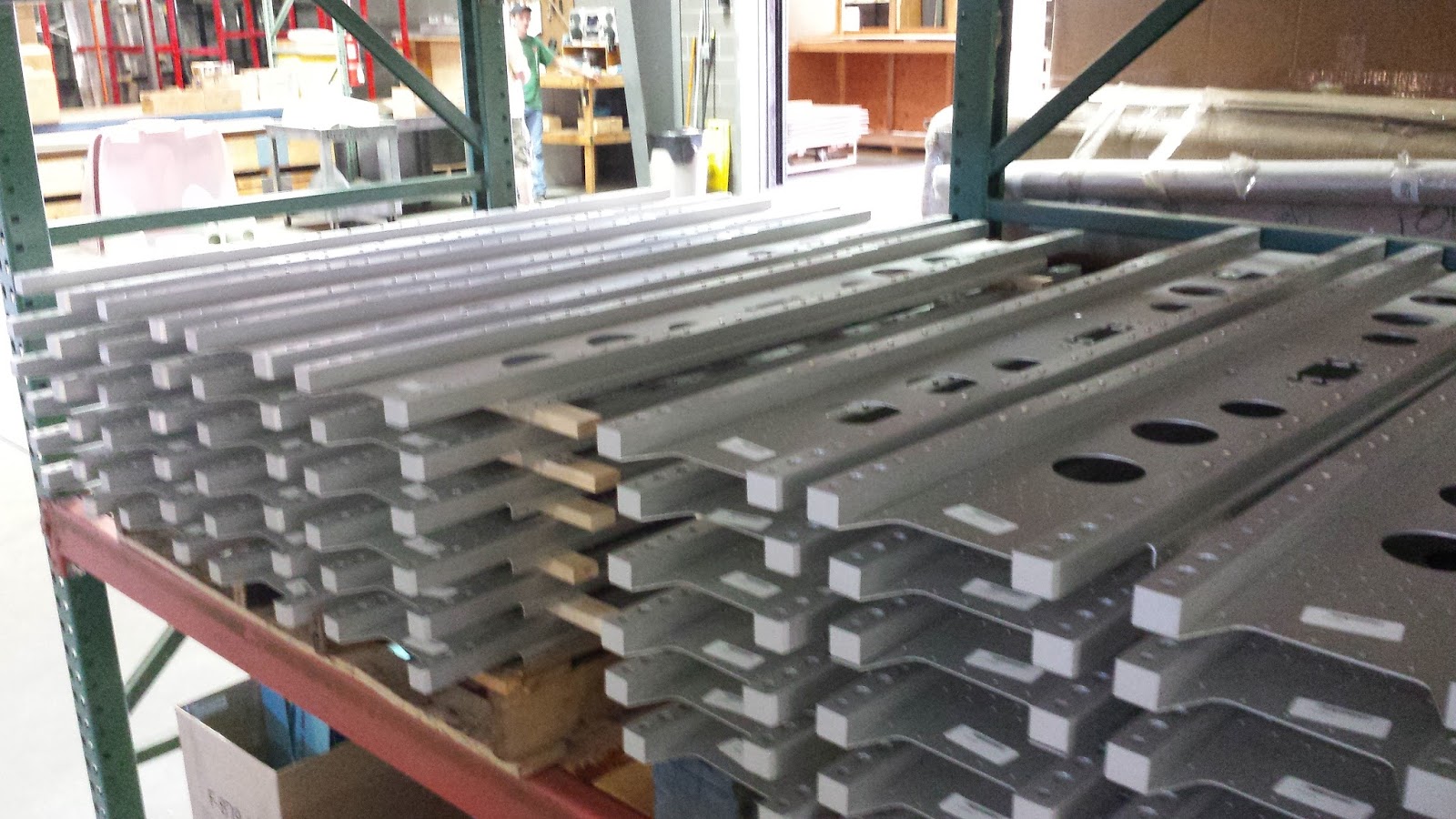
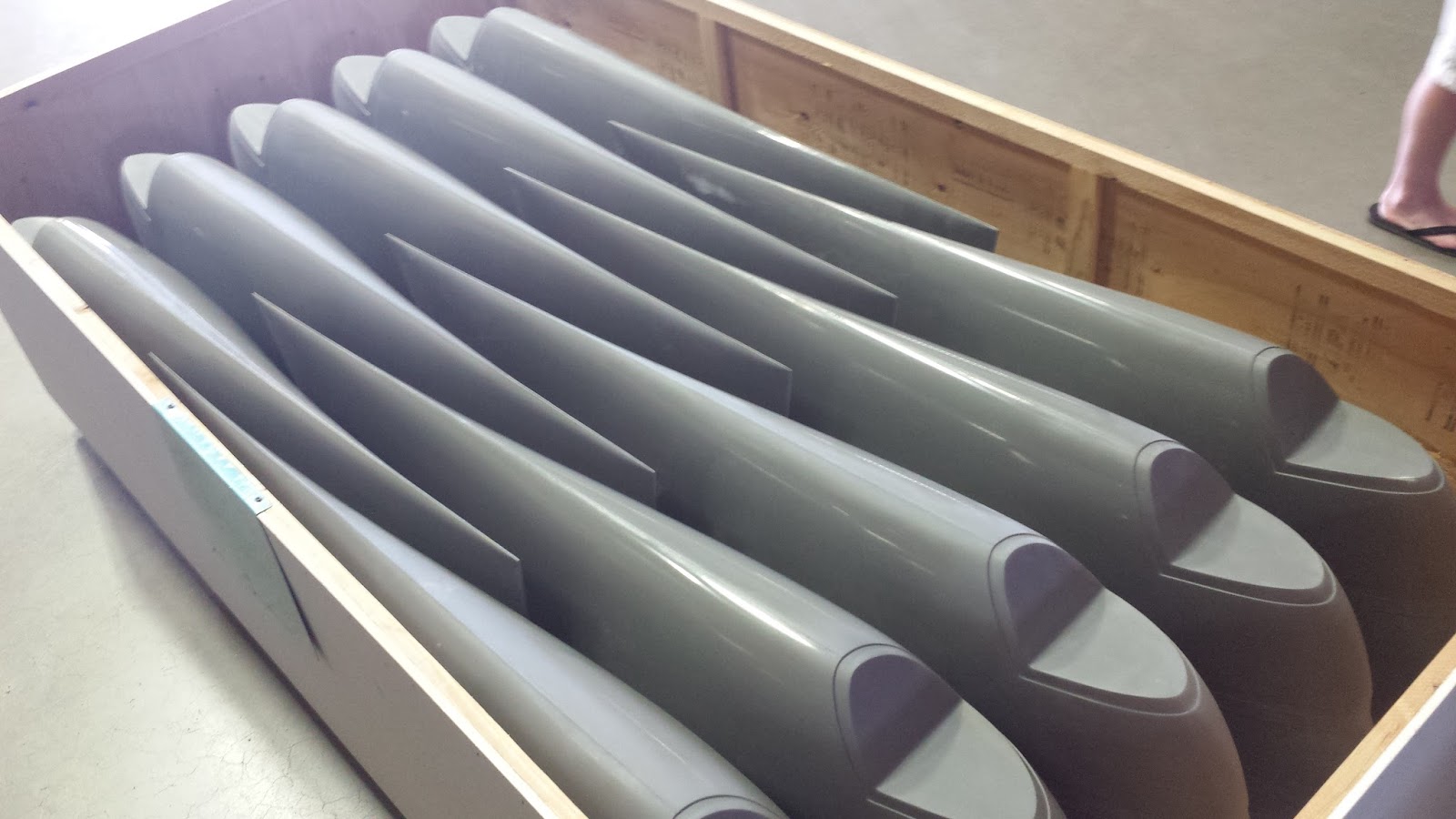
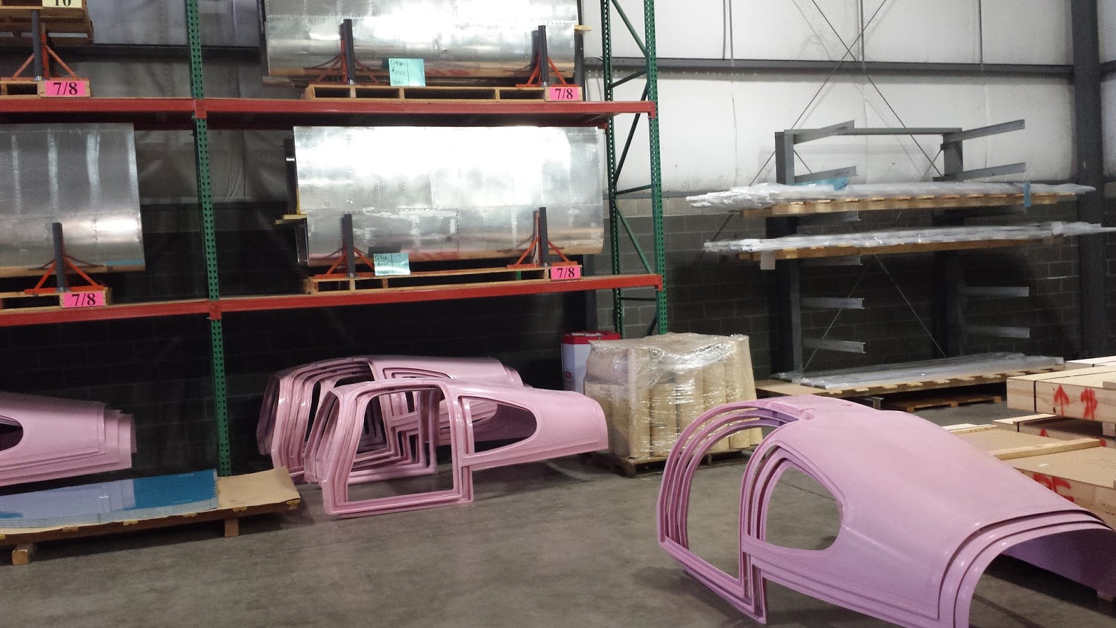
(Please forgive my inarticulate descriptions - I'm not a machinist so this was
an education for me.) We got to see the huge hangar and all of the
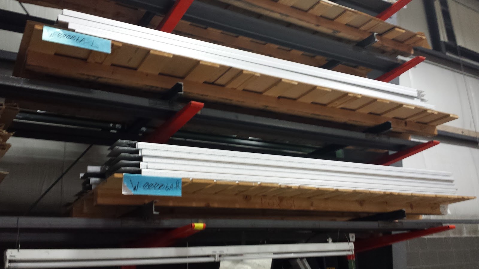
stock. Being so far into the build, it seemed as though I could recognize nearly every
part on the shelves. Ken said they have 1.5 completions per day
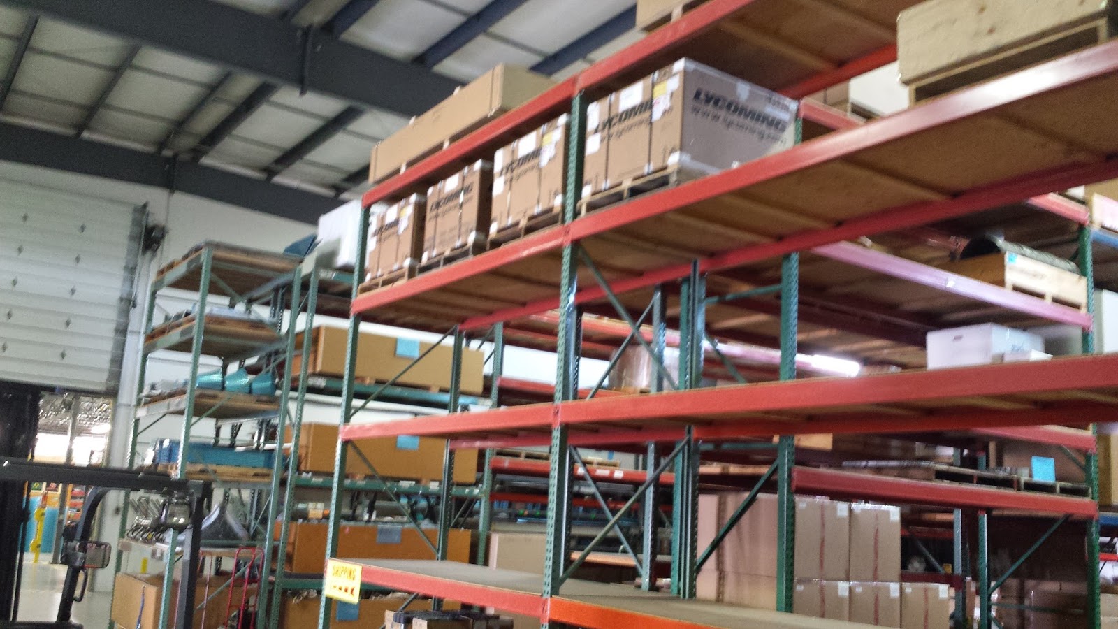
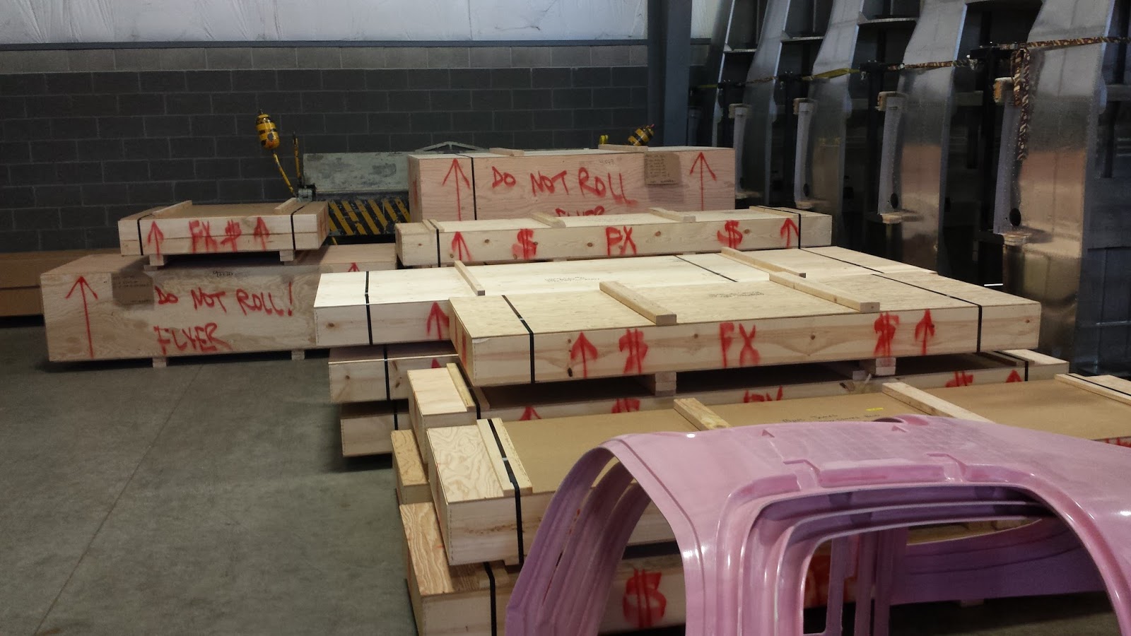
now, with more than 8000+ flying kits. We got to see a -12 fuse kit being
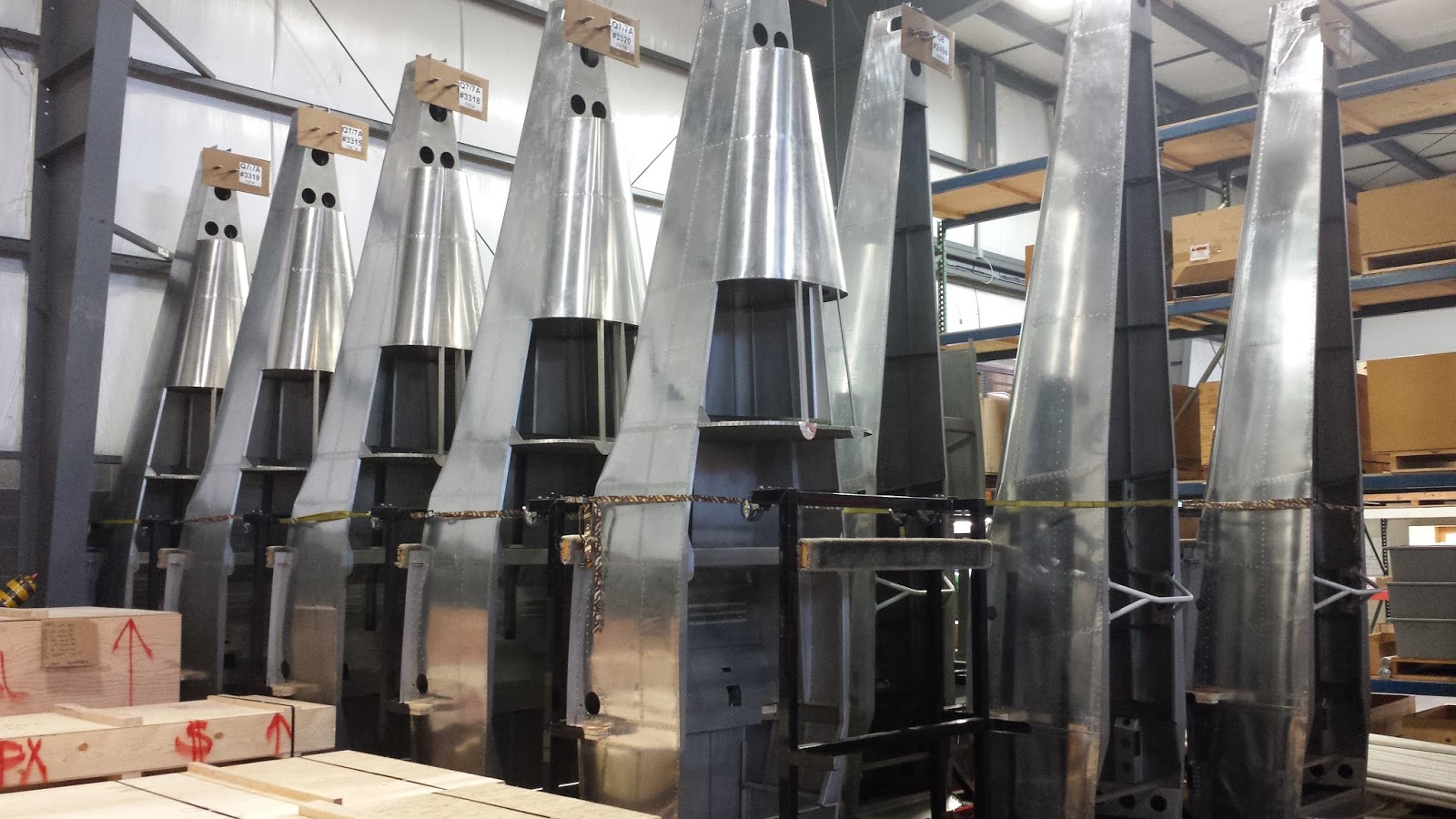
crated. There was a stack of QB fuselages (many 7s, a few 8s and a
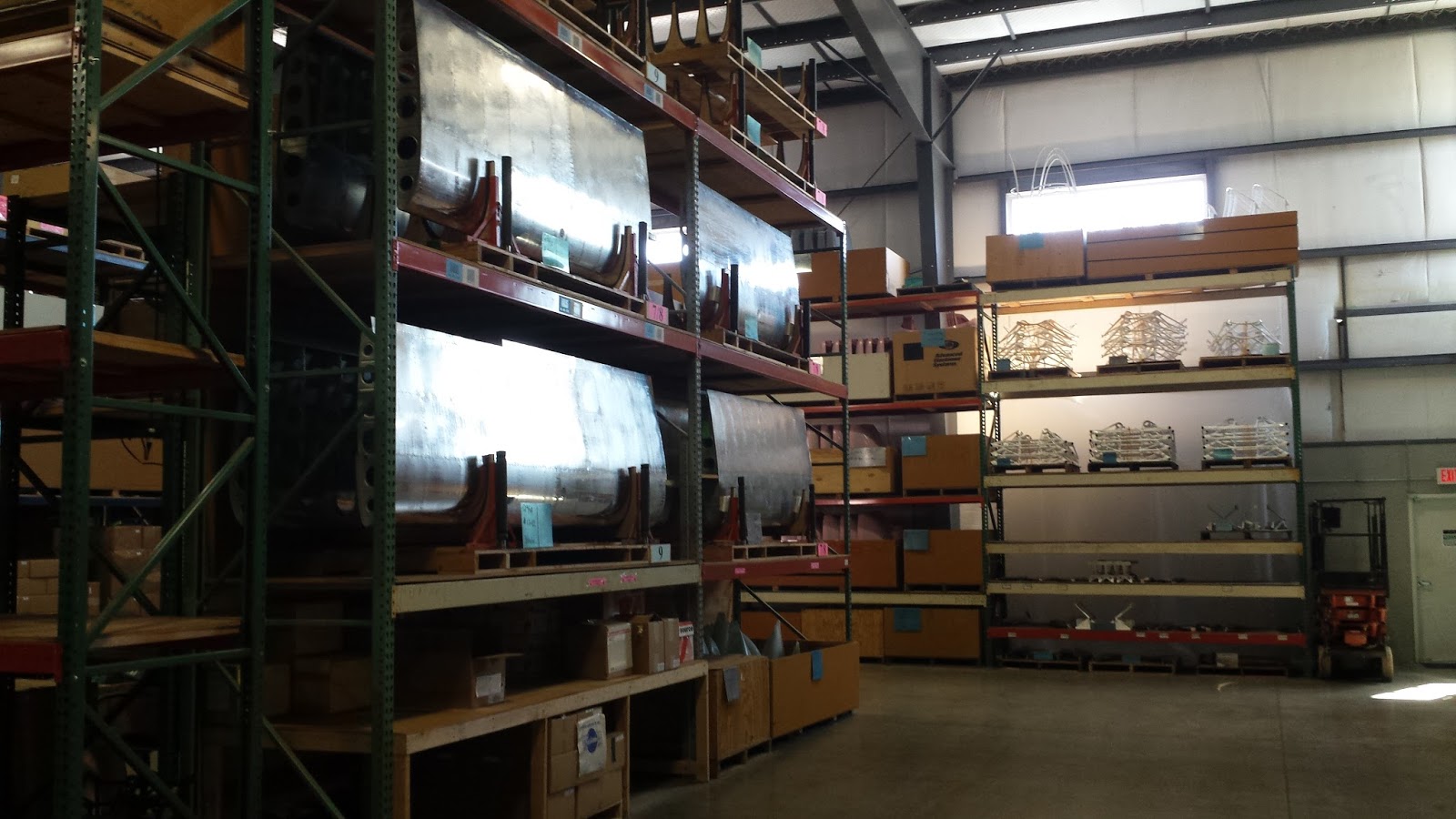
couple of 10s). A huge rack of shelves with many QB wings. Another
massive shelf with several Lycomings. Then we went into the
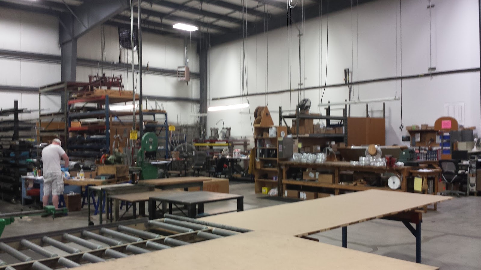
production area. I did see several -14 fuse parts (no pics,
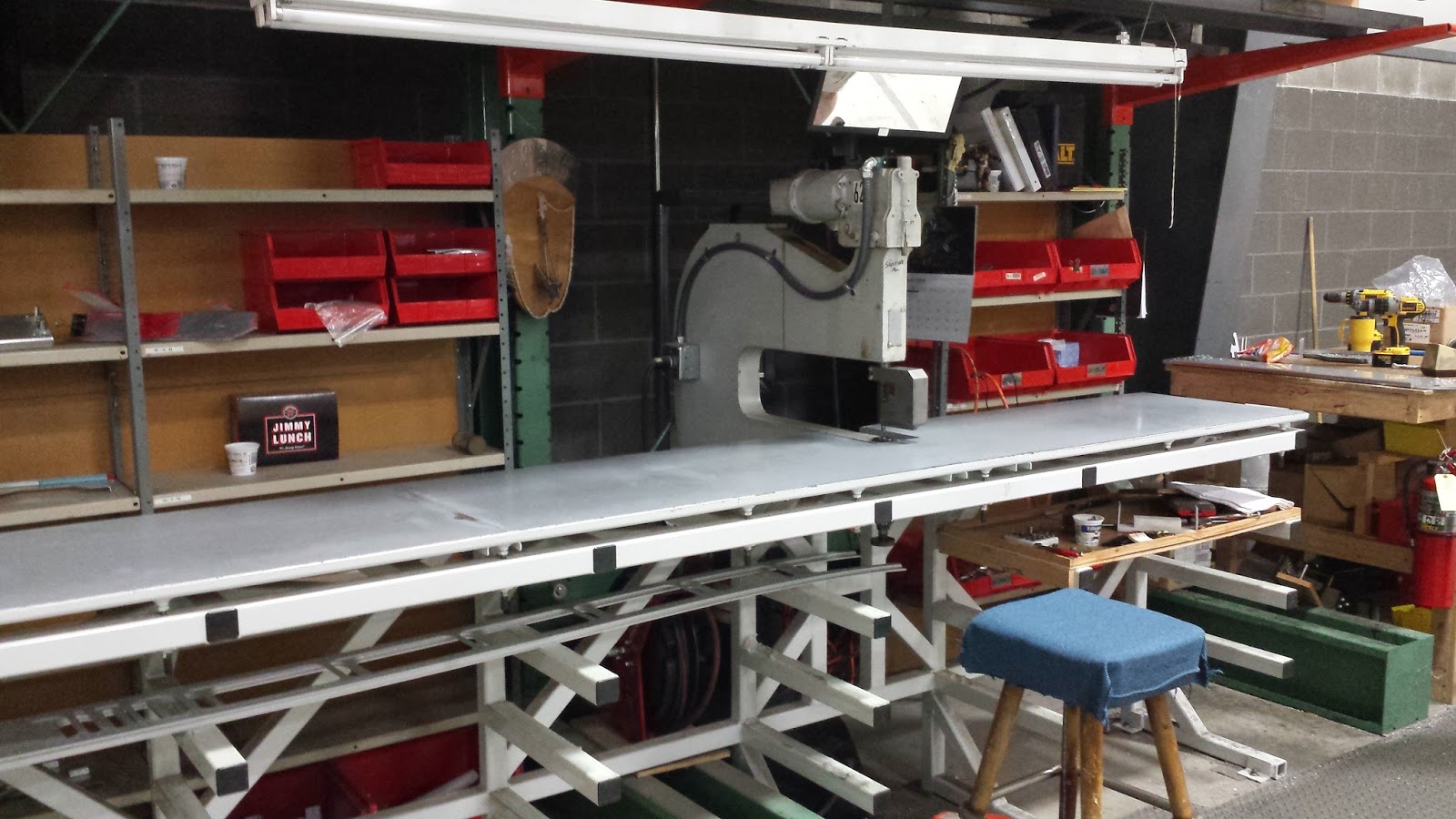
sorry). We saw several wing spars in process (they were just the
web and flanges, with nothing riveted yet), including the WWII era
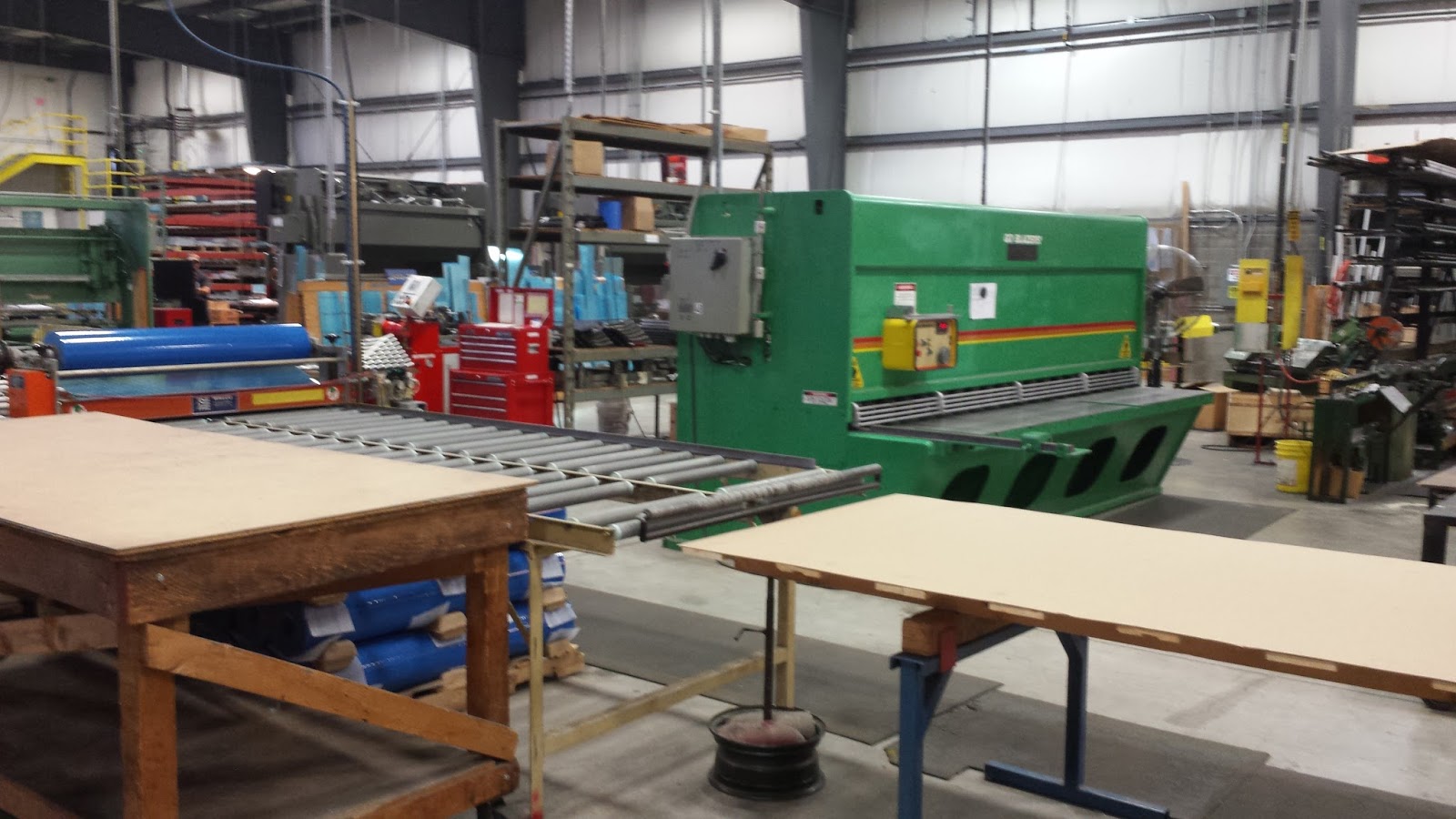
machine that rivets them. We saw the bending machines and the
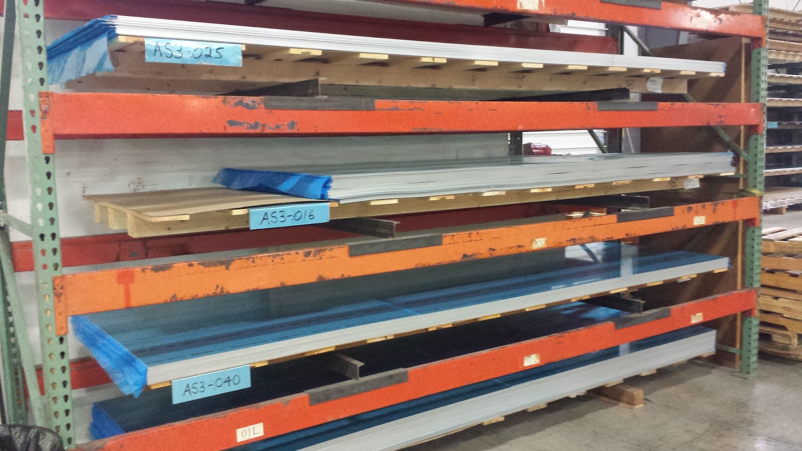
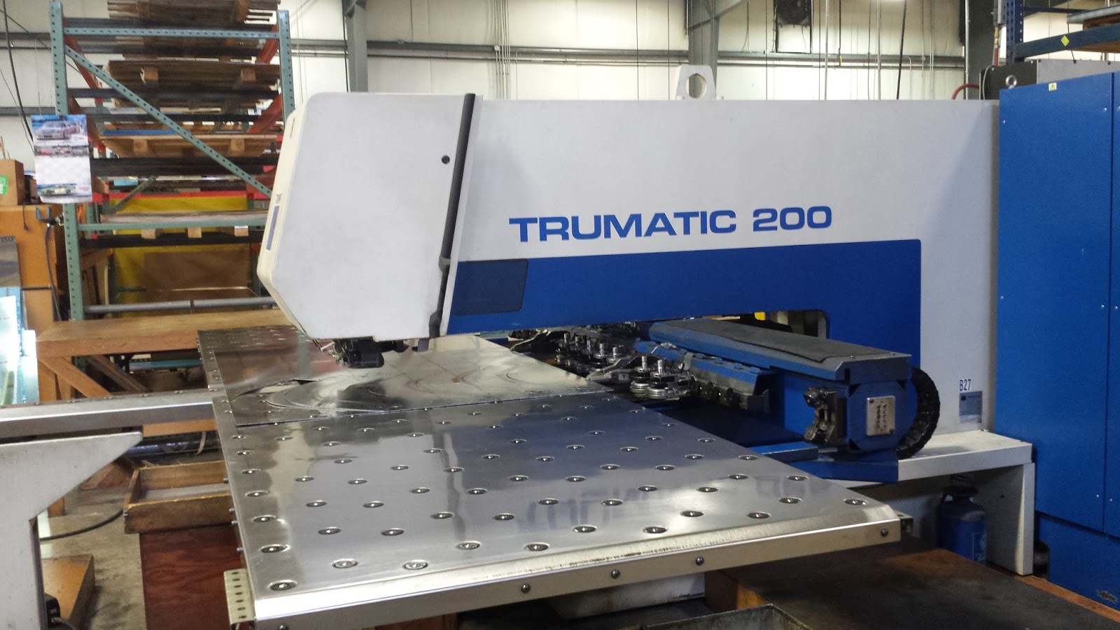
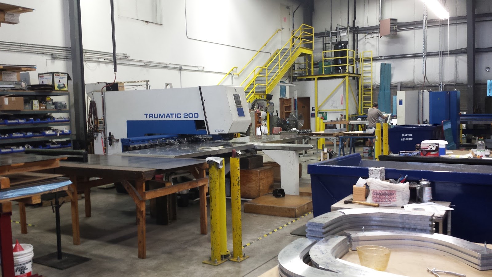
stacks of raw sheet stock. We got to see the CNC turret punch in
action as it churned out some fuselage bulkheads. Then we headed to the airplane hangar.
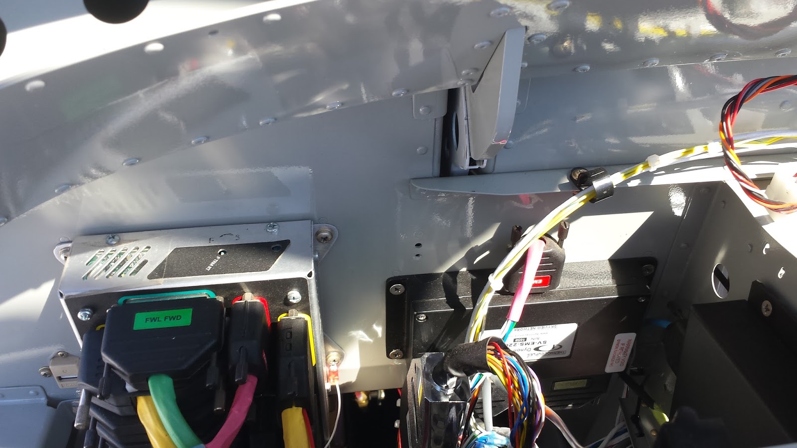
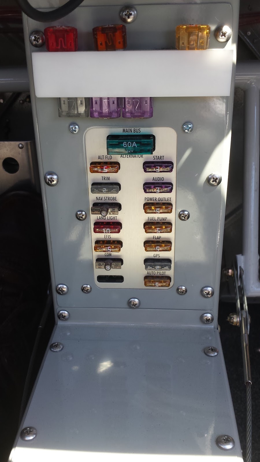
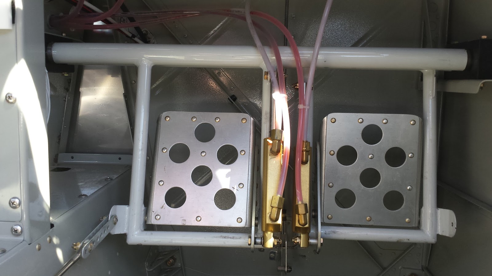
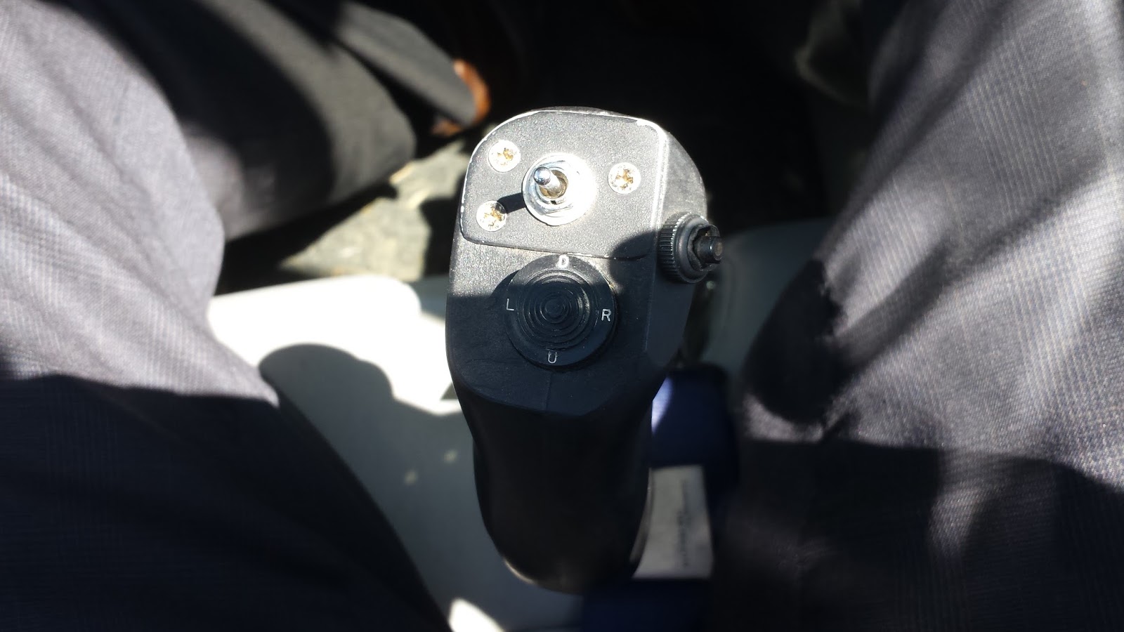
I sat in the -14A, and compared to my friend's -9A, the plane is cavernous. Wow! Lots of space! After an hour and fifteen minutes, I had to go so we could get to the next customer meeting that evening.
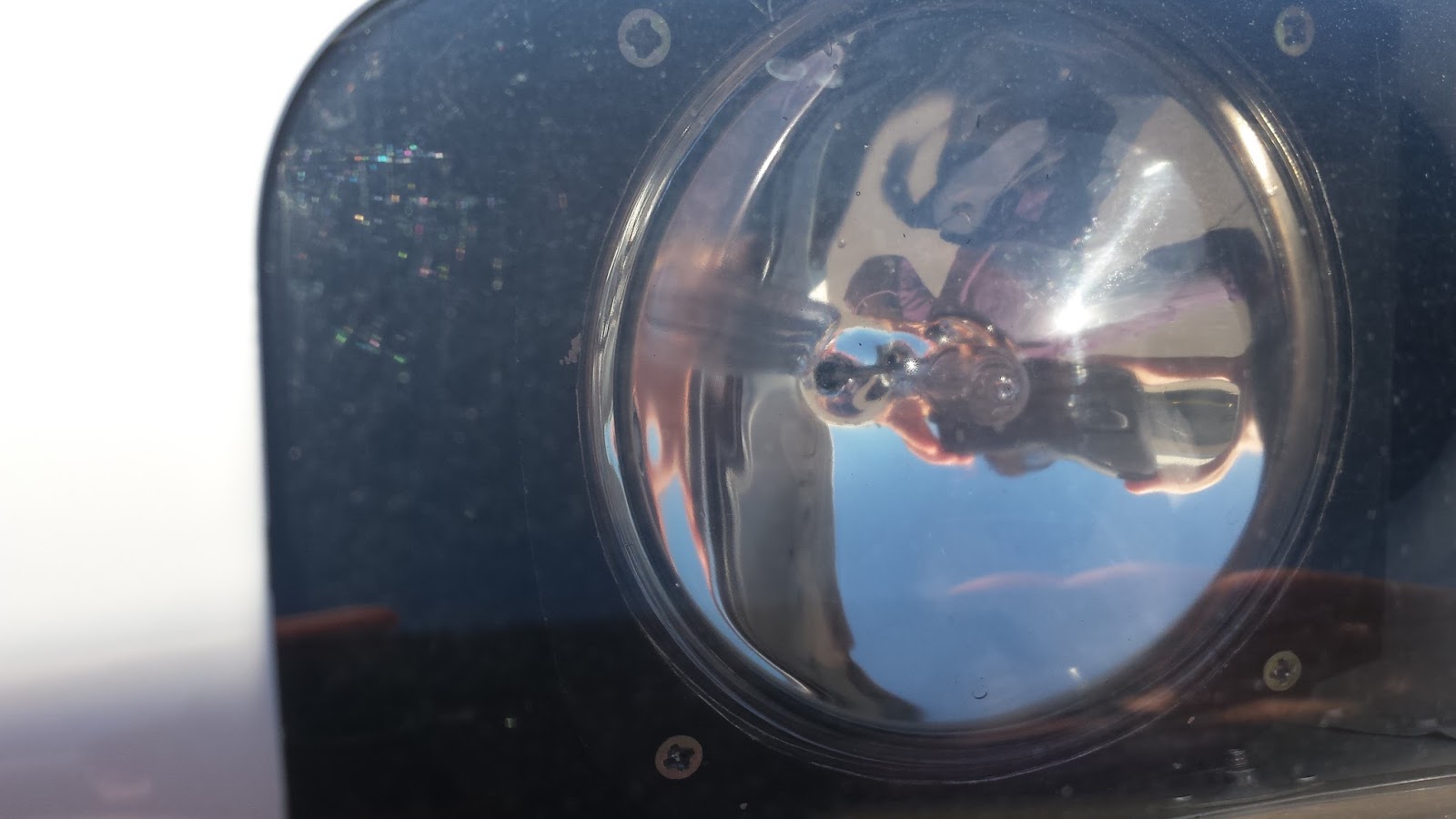
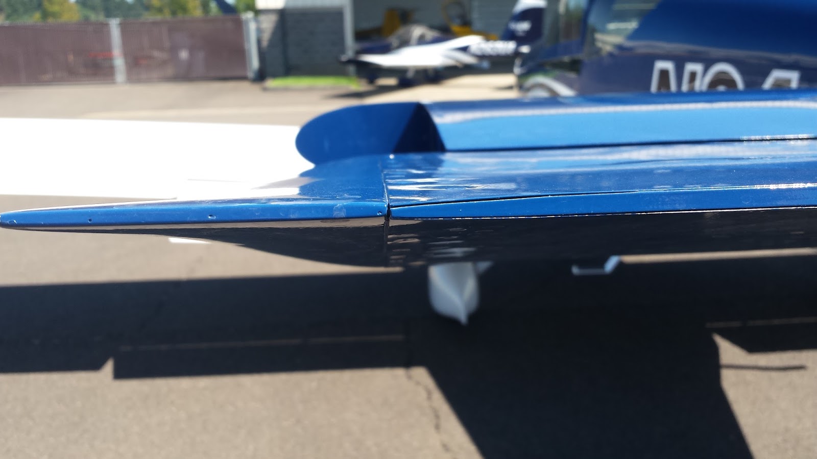
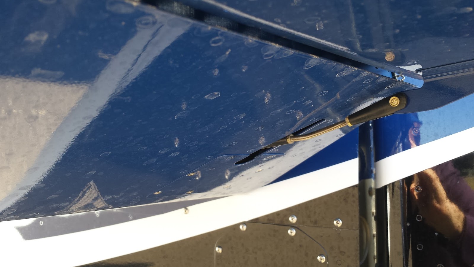
On to the pics! I asked for and obtained permission to take all of the pictures. Sorry for the occasional blurry image. I hadn't anticipated getting this opportunity so my image acquisition device was less than ideal.
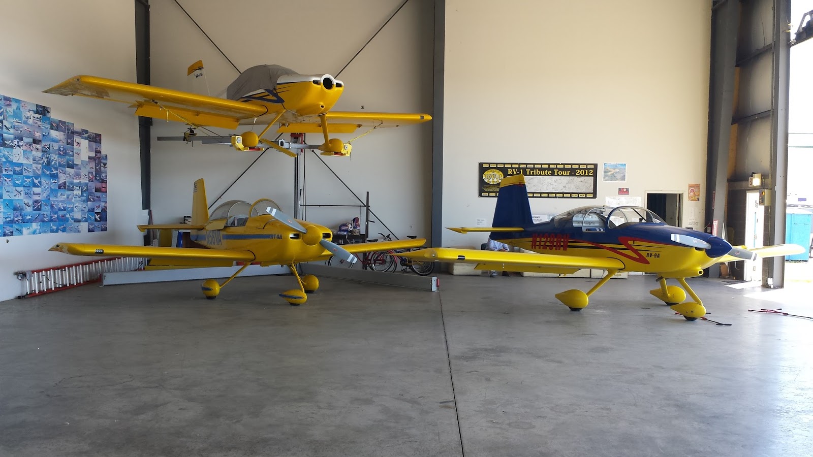
It looked like the whole fleet was there recovering from AirVenture: The -14A, -12, -10, -9A, -8,
-7A, -6A. This was the first time I'd ever seen in-person the
airplane I'm building! Ken let me have endless alone-time with the
-14. In fact, I spent nearly all my time going over every inch of
it. I did not see the TG version they're working on. It's probably
behind the door in the hangar that says "Absolutely no admittance".
I sat in the -14A, and compared to my friend's -9A, the plane is cavernous. Wow! Lots of space! After an hour and fifteen minutes, I had to go so we could get to the next customer meeting that evening.
On to the pics! I asked for and obtained permission to take all of the pictures. Sorry for the occasional blurry image. I hadn't anticipated getting this opportunity so my image acquisition device was less than ideal.
Production Tour Photos
Click on the first image to see them in a larger size. Then click through them. Short descriptions are included on this page only if you hover your mouse over the thumbnails (the descriptions do not show in the larger image viewer).
N214VA Photos
Click on the first image to see them in a larger size. Then click
through them. Short descriptions are included on this page only if you
hover your mouse over the thumbnails (the descriptions do not show in the larger image viewer).
Subscribe to:
Posts (Atom)


