21 December 2015

Shop/Wiring. Bought a crimper.

I've decided to make all of the harnesses for my aircraft by myself.  The cost to have these harnesses professionally made is an unnecessary expense for me.  Wanting to make them properly, I found that the crimper that seems to be the putative standard for the purpose is the Daniels M22520/2-01.  It can be found for an astonishingly broad range of prices from ~$250-$400, new.  Used, they can be found for much cheaper on eBay, as an example search illustrates.


The crimper has dies that are placed inside its ratchet mechanism, specific to the pins being crimped.   New, these dies range from ~$40-$70.  Used, they can be had for more than half  the cost.  


The ones of interest for me are
  • K13-1 (M22520/2-08) for male and female D-Sub pins, #20.
  • K41 (M22520/2-06) for female high density D-Sub pins, #22.
  • K42 (M22520/2-09) for male high density D-Sub pins, #22.
The K40 positioner (M22520/2-07) is for female pins in the 22 DM MIL-C-38999 circular socket, so I don't need that one.

17 December 2015

Finish: Canopy and Window. Canopy frame completed.

This is a very large section.  It has the most pages of any section among the four kits released so far (it beats Section 10 by 6 pages).  As such, it takes quite a bit of time.  In fact, the time taken to complete what's shown in this post was 45.5 hours.  The majority of that time was consumed with the many repeating steps of bending to fit, cleco'ing, match/final drilling, uncleco'ing, deburring, cleco'ing and riveting in a very specific sequence (e.g., following every fourth rivet that is set, one must check for canopy twist with the digital level).  So one can appreciate the patience needed for this section.

To start, I opted not to work on the F-14126 (rear) Window, as I deemed it safer to have a warmer garage and an experienced helper at my side, so I jumped to the canopy frame.  

Following a bout of match drilling (top row), the Left and Right Canopy Frame Assemblies are riveted together (bottom left) then joined via the C-01428 Canopy Frame Splices (bottom right).   I opted to use Napa 7220 rather than mix up a my usual batch of two part epoxy primer for these smaller jobs, though a few parts were already primed previously and are thus white rather than gray.


Most of the rivets in the assemblies can be squeezed, however the rivets attaching the Canopy Hinge Assemblies to the Canopy Frames were bucked (left).  As I mostly work solo, this required an unsophisticated jig as can be seen in the picture below.


The Canopy Rail Assemblies are interesting.  The C-01409-L/R Aft Canopy Rail Angles and C-01427-L/R Aft Canopy Rail Flanges are each fabricated at Van's from a single piece of stock and we must cut them out of their aluminum tombs (Michelangelo, anybody?).  Specifically, the Aft Canopy Rail Assemblies must be fluted so their bottoms are flat, which was a time-consuming process for me.  Furthermore, the C-01407-L/R Aft Canopy Rails must be carefully bent to match the curvature of the fuselage (left).  Eventually they get assembled (right). 


The C-01417 Canopy Frame Close-Out is cleco'd on and match drilled (left).  Be very careful that you mind Figure 3 on page 38-10 (right).  The cleco-pattern, drill sizes and match drilling pattern are very specific.  As an aside, those 1/8" holes called out for in the group-of-three holes are apparently to secure future wiring.  That isn't immediately obvious to me in the images from my August 2014 visit to Van's.


After some match drilling with the Canopy Rail Assemblies (top), the Close-Out gets riveted on (bottom two rows) as do the Canopy Splices.


The use of the wedge tool (outlined on page 5-06) is welcomed for both the Canopy Splices (left) as well as around the Canopy Hinge Assemblies (right).


Again, it is critical to ensure the frame doesn't take on a twist, so after every fourth rivet is (symmetrically!) set, the angle on both sides must be checked with the digital level.  Thankfully, my frame stayed locked on at 6.9° each side for the entire assembly process.  I don't think the magnitude of the angle is of importance, rather only that each side is the same.


The C-01411 Canopy Rail Shim must be placed properly.  There are two figures that demonstrate this placement.  The one on 38-13 (top left), to me, is initially not as clear as the one on 38-18 (top right).  So originally I match-drilled the piece incorrectly and only realized this after the majority of the canopy frame was riveted (bottom left), though thankfully before the shims themselves were riveted.   Through much fussing around with some nylon vehicle trim panel removers (which are designed to not scratch surfaces), strategic use of clecos and a chip chaser, I was able to finagle the shims into their proper location (bottom right).  Surprisingly, the rivets slipped right it without any "corrective" match drilling.

What clued me in to this error was that the AN426AD3-7 rivets called for were too short when the shim was placed incorrectly.  This caused me to take a much closer look at the plans whereupon my error was discovered.


Eventually, the assembly gets riveted together.  I found that the AN470D3-4 rivets called out for along the Canopy Frame Closeout were too long, as determined by my sizer.  Additionally, I wasted a lot of time trying to squeeze those and eventually terminated the effort in favor of buckin' 'em.  It's faster and cleaner.


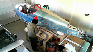
And notice that with the canopy up, the garage door should not be opened (with the airframe on its gear, perhaps this won't be an issue).  This suggests some prudence in putting a garage remote controller in the fuselage should the door be opened with the canopy up by an unscrupulous, unsavvy party.  Also, with the uncompleted frame temporarily placed, I took this as an opportunity to ensure that my deeper instruments would not conflict with the canopy Close-Out, as illustrated in this post.


For the C-01405-L/R Aft Canopy Frame, we must use the C-01442C Aft Canopy Fixture to ensure the parts are properly aligned (left).  Originally, I placed the fixture in the proper location during the first alignment procedure.  However, following the initial riveting of the Canopy Handle Assembly, I used the fixture incorrectly.  This caused the parts to be improperly aligned, so the frame parts were scrapped and replaced to the tune of $80, shipped.

I noticed this error when I went to rivet the parts together and saw that the holes no longer lined up (since I now had the fixture properly placed rather than improperly placed when it was match drilled).  Correct placement is shown on the left image.  Reviewing my time lapse video confirmed that the fixture was improperly placed, as seen clearly in the right image (where it is also apparent that building in my cold garage is a far less comfortable affair than the climate controlled basement in my previous digs).  Ugh.


In keeping with my red accent theme throughout the interior of the aircraft, I painted the Canopy Handle Assembly red (whilst again painting the canopy frame the same color as the interior as with the Rollover Structure).  So the part should look like the below images.


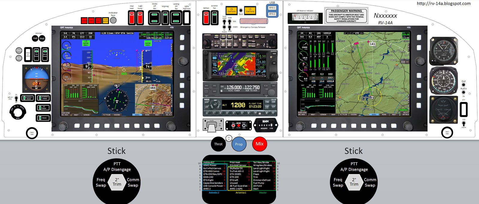
And it made sense to paint the canopy frame interior prior to match drilling the canopy window (other builders concurred) as I don't anticipate a lot of handling in areas that are vulnerable to scratching.  I decided to paint the C-01445-L/R switch brackets red too (which induced me to update my panel with an indicator light for the canopy).


No pictures of the completed assembly on the aircraft.  I'm waiting to complete the rear window.

05 December 2015

Avionics/Panel. Instrumentation fitment in panel.

The C-01417 Canopy Frame Close-Out hangs below the C-01418 Canopy Skin a significant length.  The canopy may not close if instruments on the outboard top halves of the panel project too deeply forward of the panel.  A builder with a professionally built panel ran into this issue.


The first step in determining if my instruments sit too deep is to temporarily place the canopy on the aircraft.  Then print out to-scale outlines of the instruments and tape them in the precise locations using a flashlight to align the paper with the panel through the nutplate holes.  Because the TruTrak ADI2 projects more than 6.5" beyond the panel, I'm specifically concerned about its depth.  So I cut out the 2.25" square that represents its placement so I can place the ADI2 in the correct location when testing with the canopy down.


As is visible in this image with the canopy down, the ADI2 has a clear trajectory to the Canopy Frame Close-Out and it turns out that the former will prevent the latter from closing.


So I had to move the ADI2 even lower on the panel to clear the impinging Canopy Frame Close-Out.  Because this then compressed the space available for the switches underneath the ADI2, I had to reorient the lower four switches to the horizontal to make space for their labels.  Thus, my panel will now look like this.


04 December 2015

Finish: Wheels assembled.

I put together the wheels.  It was a 3 hour affair for me as I had some learning to do.  After scouring my local grocery store for talcum powder and realizing that baby powder is composed of corn starch, I purchased Tire Talc from Spruce (that stuff makes a mess) as part of another bolus of parts I needed.  Update 16-Jan-16: If you look carefully, the main wheel in the left image below has the valve stem aligned with a pink dot (which looks red at night).  I had to disassemble and redo both main wheels to align with their red dots.


I did pay heed to the discussion on VAF about the nosewheel in the kit being the wrong size (Grove NW501.25 vs NW511.25), discovered by another builder who documents his build on his blog, specifically detailing the nosewheel issue on this page.  A terse summary of the issue is that for the wheel provided in the kit, the valve stem will have an extended protrusion, causing it hit to the fork.  The NW511.25 does not have that issue (below, right) and retains the use of the same tire and tube.  Matco allowed me to swap my unused NW501.25 for the NW511.25 for $21.49 plus nearly $20 shipping (though the box came with $3.25 postage due, so shipping was more than $23), putting the cost of the exchange at nearly $55 when the shipping for the old wheel is included.  A reasonable cost, in my opinion.


However, also in that discussion and blog post above is an outline on why one might want the Matco axle over the one provided in the kit by Van's.  In fact, a builder verbosely documented his thoughts on the axle here as it relates to the similarly equipped RV-10.  Summarily, the Van's axle and spacer (below, left) doesn't let you adjust the bearing preload independent of the load imposed by the fork.  This may lead to the parts rotating against the fork, causing undo wear manifesting in shimmy, indicating a wheel that isn't rigidly attached to the fork.  Whilst I'm no expert in this area (well, in any area really), I opted to use the axle and spacer provided by Matco (below, right) for the additional cost of $62.66 and $12.32, respectively.


As shipped, the whole changeover was $116.19 to Matco, plus the $3.25 postage due when delivered, plus $10.06 additional to ship the original nosewheel back to them.  So $129.50.  If one were to delete the parts NW501.25, two of  U-1023, and U-1009 from the finish kit in favor of NW511.25, WHLAXLE24 and WHLA24SPKIT from Matco, I'm sure the total cost of this change would be reduced significantly.

Finally, it's worth pointing out that the nosewheel lacks a grommet for the valve stem whilst the main wheel have the grommet.  I put in an email to Matco inquiring about this curious omission.  Their reply was "There is no grommet for the valve stem hole". 

21 November 2015

Fuselage: Roll over structure. Completed.

The roll over structure construction is quite straight forward.  A lot of cleco'ing and match drilling is required, along with copious care to ensure parts are mated aligned and remain so.

The F-1231E Roll Bar Splice Plates are riveted on with the F-01431A-FL/FR Roll Bar Frames temporarily placed on the F-1231D Roll Bar Bases to lock the frames in place (below).  I was able to get the forward frames to easily align together with the bases and splice plate.  The aft frames, however, required significant prodding to achieve alignment.


The frames are then fully cleco'd with all of their requisite parts, so that match drilling can commence.  Here, every other cleco has been removed to support the match drilling process, later replaced with copper clecos (as an aside, I actually had to buy more copper clecos to complete this step).


The F-01431D window shims need to be countersunk for CS4-4 rivets (remember to use your 120° countersink).  Those shims aren't very thick, so without additional support, the holes would be hollowed out by the countersink pilot.  Thus, I chose to countersink the shims when they were cleco'd on the roll over structure.  Also, prideful rivets aren't desirable here, as the rear window rests on the shims.


The parts are then uncleco'd, deburred and taken out to pasture, where they are cleaned, acid etched, scuffed, cleaned again, then primed (I opted to use Napa 7220 rather than mix up a batch of two part epoxy primer for such a small job, though a few parts were already primed previously and are thus white rather than gray).  The parts are riveted together.


Some match drilling into the roll bar bases...


Not yet knowing what my exterior paint scheme is going to be, and realizing that once the rear window goes on, painting the roll over structure becomes difficult (and impossible for the upper arc underneath the window), I decided to paint it the same color as my interior.  I considered painting it black and even red, but decided that using the interior color would give me more options for the later, undefined, exterior paint scheme.

I had painted the F-01432A Roll Bar Brace red when I previously painted some other smaller parts red.  I painted the brace impulsively, not really giving much thought to how that would affect the options for the exterior scheme (so I guess I'm going with some red).  And, I thought it would create some unobtrusive eye candy if I were to paint the C-01432 Bushing Doubler and C-01433 Bushing Covers in some contrasting colors.  So the scheme should look like the below:


Following final riveting, the final product is as below.