29 December 2016

Avionics: GPS antenna shelf.

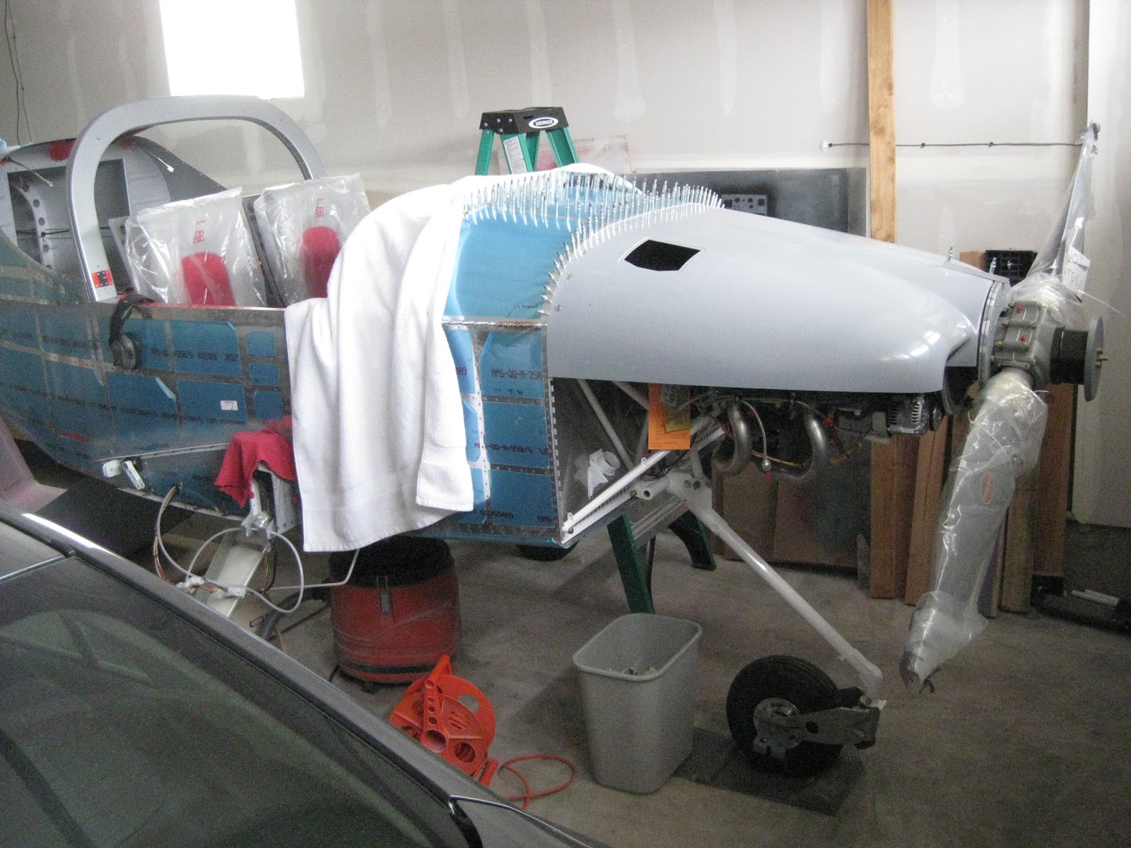
Many folks put their GPS antennas on the glareshield.  I think that's a great location, however I wanted mine to be hidden (other than the one for the GTN-650), so like many others, I wanted it under the cowl.  For that I had to create a shelf.

The SkyRadar DX, GRT AHRS and TruTrak ADI 2, each have a GPS antenna.  However, one is magnetic, one uses adhesive and the last one uses screws.  So I replaced them all with Linx Technologies antennas (MCX and SMA types).  These antennas are tiny, mount with screws and have the proper specs for the purposes intended.

I secured some scrap 1/8" thick aluminum left over from when my first panel revision was cut, match drilled a 3/4x3/4" angle into it, then match drilled antenna mounting holes.


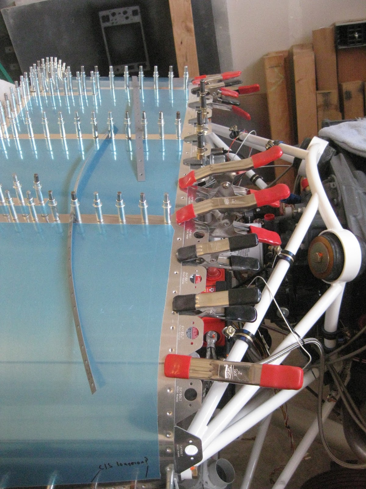
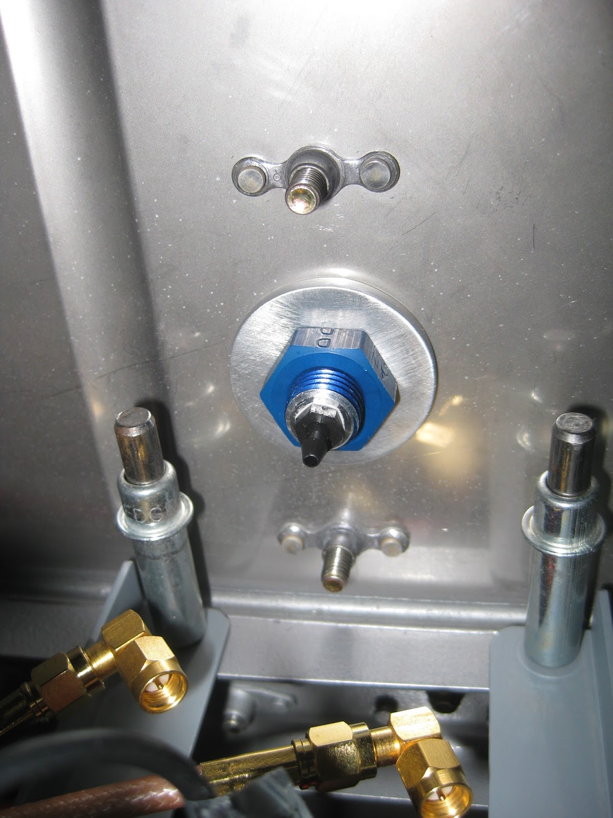
Then I match drilled holes into the firewall, above the VA-168 Sender Mount, attaching nutplates to the firewall so that the shelf can be easily removed if necessary.  The shelf was primed and the antennas were attached with 4-40 screws.  This picture brings to mind the "array factor" of an antenna array's radiation pattern.


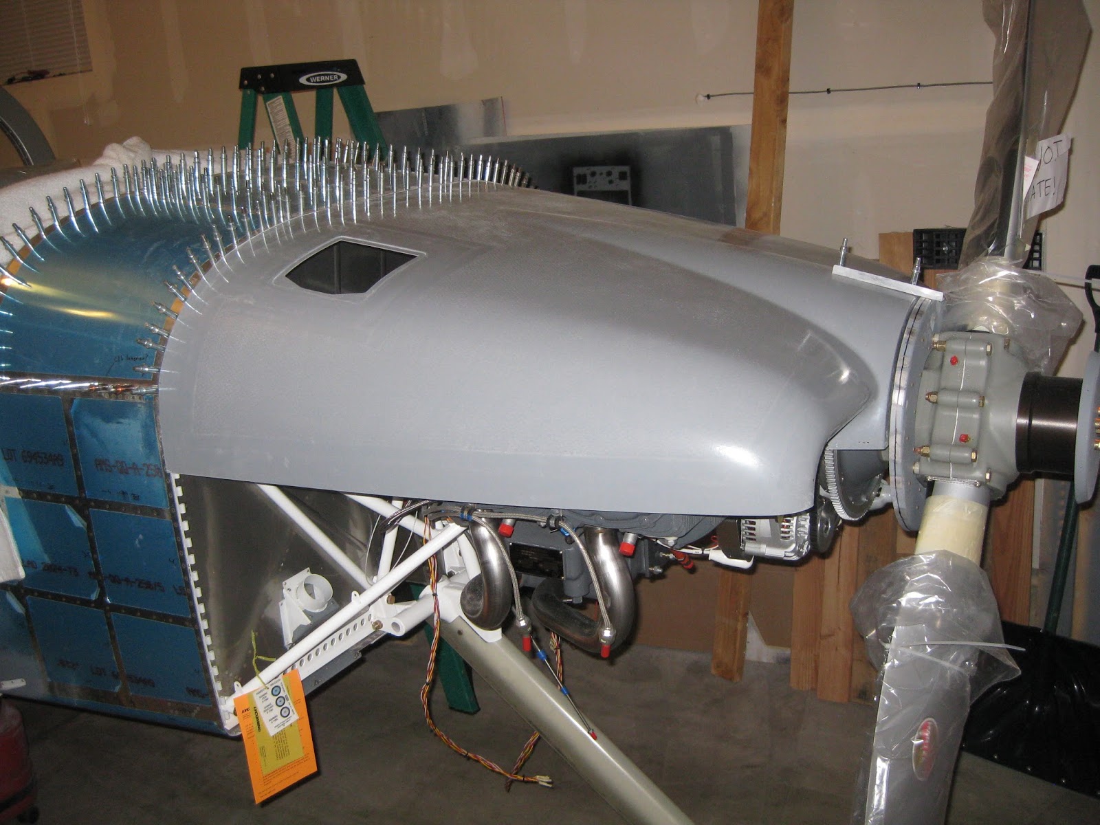
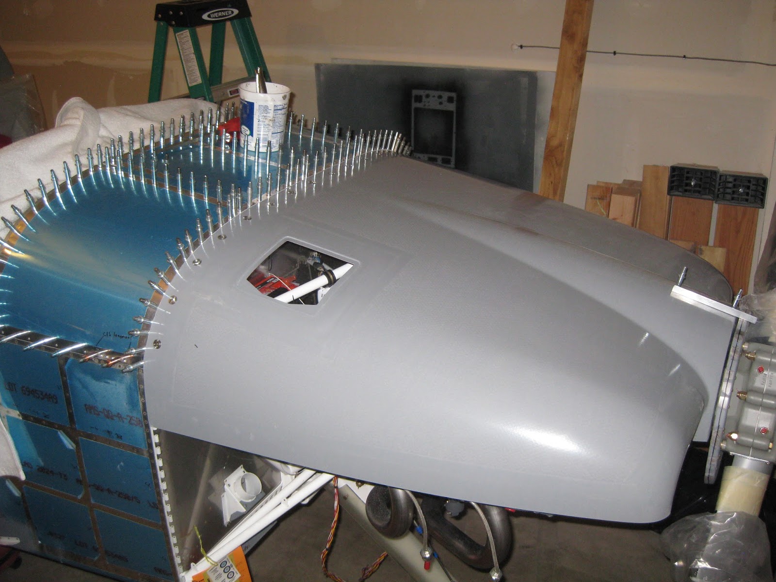
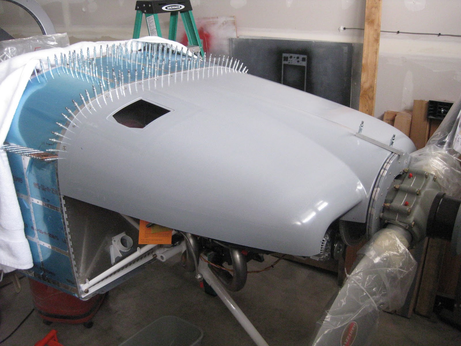
Here is where the shelf shall sit when in operation.


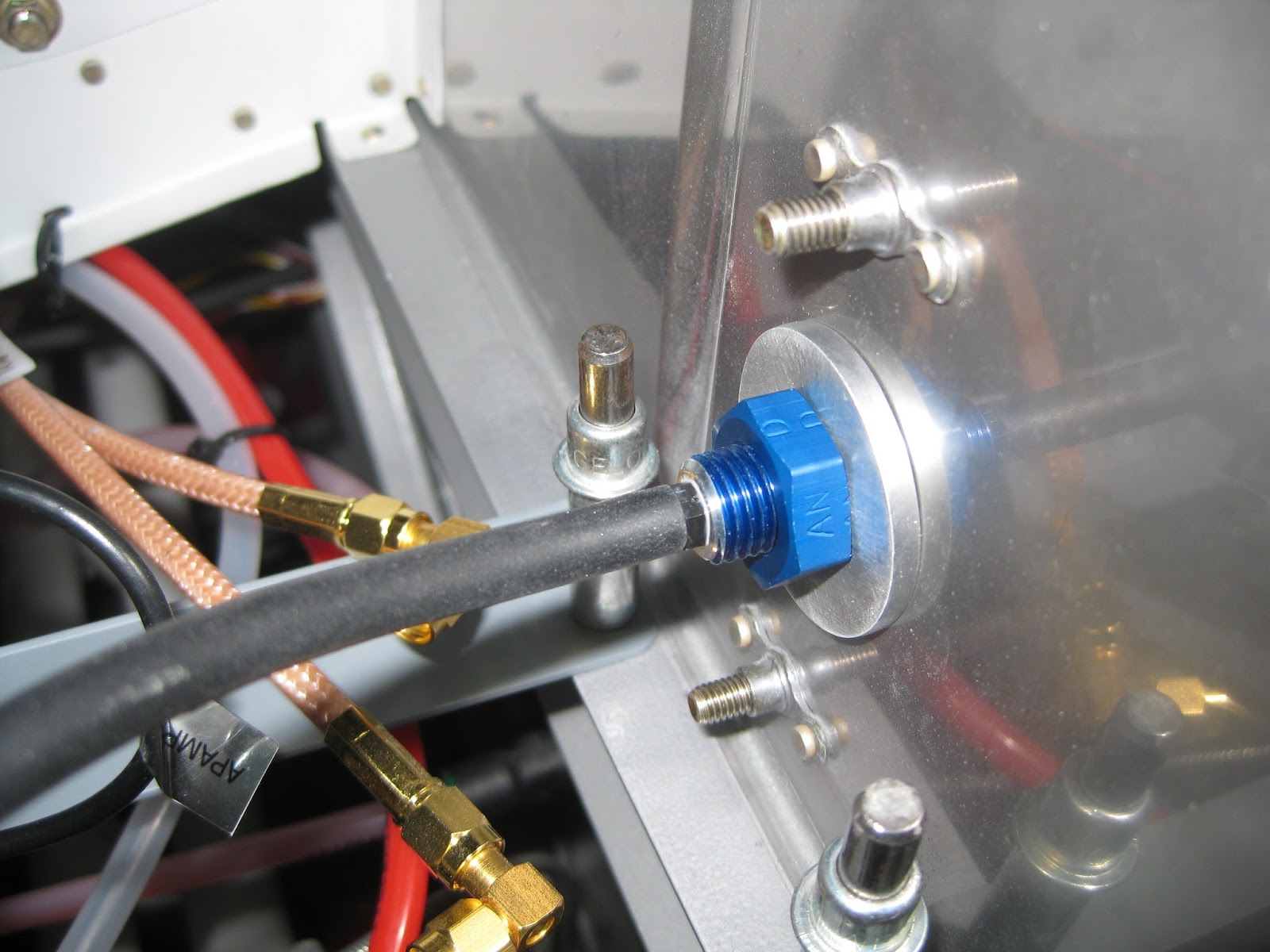
If it turns out that they sit too far below the cowl (so that the line-of-sight angle subtended aft is too shallow), I can flip the mount around and install the antennas on the other side to get them higher up.

27 December 2016

Avionics: Modified fuse block to support buses.

I wanted to use three buses for my avionics.  That topology is explained in this earlier post.  It required 29 fused positions.


Turns out that, short of ordering in lots of 1,000, obtaining a fuse block that has the three buses as I wanted them (13, 9 and 8 positions), wasn't going to happen.  So I obtained a 30-position fuse block that is independently wired.  The 60 A breaker for the alternator is a "Mechanical Products 1648-009-060-015" from Waytek.

This required me to have power distribution blocks, in the same way one would have ground distribution blocks.  I needed three of them, one for each bus.  So that's what I designed and implemented.  Below are the Master and Avionics 1 buses (top left) and the Avionics 2 bus (top right).  They are unsightly, as the hot side of each fuse is connected to the respective bus.  However, they indeed functioned.  The bottom left image shows the multitude of wires going to the fuse block.  And the bottom right shows that it can look pretty when finally installed.


But, I just didn't like that setup.  There was no good way to cover the positive distribution blocks, which represented a risk I wasn't comfortable with.  Then, one fine December day, it struck me just how to fix this problem...

First I cut up a bunch of wires and attached the fuse blade terminals to each wire.


Then I created my own buses by using high gauge wire to connect each fuse position appropriately.


Each bus wire was tinned (left) and then each fuse wire was soldered to the its bus wire (right).  It's worth noting that a 140 Watt soldering iron was necessary to generate enough heat to make this happen.  There is a lot of wiring here acting as a very effective heat sink.


Each bus was then insulated with heavy poly tubing.  This reduces the possibility of chaffing (especially since the solder wasn't smoothly applied) and shorting.  Below shows the nine position Avionics 2 bus.


Here is how the 13 position Master bus was setup.


After ripping out my original setup, I could install this new one.  Here is the back side of the new fuse block after it was installed.  Each of the three buses is apparent.


Four wires go into the output of the 60 Amp breaker.  The input of course being the alternator.  The output has the battery, the Master bus and both Avionics 1 and 2 buses.  The visible metal is the only portion of the positive polarity in the electrical system that is exposed.  I'll find a way to cover it gracefully.  A MS-25171 nipple may be the way to go.


This was exactly 16 hours of work.  A great waste of time and money to fix a self-created problem.

23 December 2016

Finish: Cowling. Upper cowl mounting completed.

First the two cowl halves are aligned and match drilled.


I didn't want to use hinges at the top cowl since they would be somewhat difficult to remove and reports of eyelet breakage and burnt appendages have surfaced.  So I decided to use quarter turn fasteners from SkyBolt.  First, the scalloped flanges are positioned prior to match drilling (left).  It's worth noting that with 3" spacing, I could fit 13 flanges but with 2.5" spacing, I could achieve 16.  So I chose to go with 2.5" spacing.  The flanges need to be bent to follow the profile of the firewall top (right), thus each flange was numbered according to its position.  Also, as can be seen, I cut off 0.5" on the joggle of the flanges.  That wasn't necessary.  It's worth noting that the F-14134A Cowling Hinge Shim caused the cowl to sit too low when using the quarter turn fasteners.  So I removed the shim.


Shown below is following match drilling of the flanges into the skin/firewall.  The paper was just to prevent swarf from accumulating in engine parts.


Here are the two outboard-most flanges showing how well they ended up being positioned relative to the start of the side hinges.


With the flanges now cleco'd in position, the upper cowl can be supported on its aft edge.  Thus, after it was placed, plumb bobs, a straight edge and a digital level were used to ensure a level cowl, as outlined in the plans.


Since the aft edge of the cowl has not yet been trimmed, the upper cowl sits very far forward (left).  After trimming the aft edge (by removing the cowl, trimming and replacing the cowl exactly 28 times), the requisite 3/8" clearance at the spinner is achieved as indicated by the very loose fitment of an AN3 bolt in the gap on each side (right).


These two images illustrate how careful I was to ensure the aft edge fit the edge of the skins following filing.  I suggest making a mark, as I did in the right image, on the cowl to indicate where the edge profile of the upper forward skin changes from vertical to angling forward.  This will help ensure you file the associated notch in the upper cowl properly.


SkyBolt includes little cleco adapters that you tape into the holes of the flanges so that you can drill through the cowl to insert a few clecos into the flanges.  You can see a few of those adapters in the picture below.  However, the cowl is very thick, so locating exactly where to drill those holes is nearly impossible since the light scatters so much.


So I opted to tape the cowl in place (not shown in the picture below)...


...then, using the flashlight, I would determine the approximate location of where I should drill holes into the cowl for the fasteners (left and right top).  I would then blindly drill a hole (left bottom) and carefully enlarge and adjust its center with the unibit to match the proper location (right bottom).


Eventually, all holes were drilled (left) and each grommet was inserted into the holes, followed by the fasteners (right).


A fastener inserted.


The flanges where then primed and the receptacles were riveted in (left).  Then the flanges were cleco'd back into position (right).


The cowl was placed and the quarter turns were locked (left).  Next, the pins were pulled (center).  The masking tape was included to ensure the receptacle anti-lock pins didn't fall out.  And finally, the receptacles were set (right).


Upper cowl mounting completed.  Only the oil door remains.


It's worth noting that, with the quarter turn fasteners, the F-14134A-L/R Cowl Hinge Shims caused the upper cowl to sit too low where it abuts the F-01471 Forward Top Skin.  I omitted the shims.

17 December 2016

Avionics: MAP sensor connection

Since I am using GRT's avionics in my bird, I cannot use the kit's default provisions for the MAP sensor.

Here is an AN816-4D nipple attached to the port under cylinder 3 on the engine.  I used a VA-118-1 22" Brake Hose Assembly from Van's to bring that to the firewall.


I drilled a hole in the firewall between the two holes originally for Dynon/Garmin MAP sensors.  This hole has a VA-170 Restrictor Adapter (left), attached with an AN Spacer, 4D Washer and AN924-4D Bulkhead Nut (Right).


The GRT MAP sensor line is then connected.


Though not shown, the parts passing through the firewall were later sealed with fuel tank sealant.

16 December 2016

Avionics: Oil pressure switch

My panel design includes a Hobbs switch and an "Oil" indicator light.  I wanted those to function as as result of operating oil pressure.  Thus, I needed to add an oil pressure switch to the VA-168 Sender Mount on the firewall.  However, the circumference of that switch requires the Sender Mount to have a spacer underneath it.  This trail was blazed by previous builders.  I merely copied them.

Here is the 1/8" spacer after cutting and match drilling it.


Spacer installed.

Oil pressure switch apparent.  I obtained it from Van's, part "IE SPDT PRES-15 SW".  It's manufactured by Nason, part SM-2C-015F.  I later redid the common wire as the one in the photo broke after mild handling.  The wires passing through the firewall have not yet been secured with fire sleeve and RTV.


This switch has three terminals:  Common (C), normally open (NO) and normally closed (NC).  The C goes to ground, as shown by the black wire above.  The yellow wire goes to the "Oil" light on my panel and is connected to the NC terminal.  This provides ground to the panel LED when the oil pressure is <15 psi, thus switching the LED on.  When the oil pressure exceeded 15 psi, the ground is removed and the LED turns off.   The NO terminal is connected to the HOBBS meter.  Thus, when the engine has oil pressure >15 psi, it provides ground to the HOBBS (which has +12V when the master is on), thus turning it on.

Here's a shot of my panel's independent indicator lights.  Here, you can see how I made the test circuit so when you press the switch on the right, all indicators annunciate (to determine if any lights are burned out).