
This was a very difficult section for me. The U-01401 Main Gear Leg as provided doesn't fit through the U-01402 Lower Gear Brace. I came to understand that some builders beat the leg into place by using a heavy hammer. However, I believe that approach isn't ideal as it places the parts in tension, which could lead to later failure.

A consultation with Van's elucidated that during the Main Gear Leg's manufacture, the heating and bending processes can cause the edges of the leg to bow outwards, effectively increasing the thickness of the leg (in the fore-aft/longitudinal axis). Thus, it is acceptable to file down the edges to achieve proper fitment. The left image shows, after some initial filing, the contact area that was binding the Main Gear Leg and Lower Gear Brace. A few iterations of 1) gently filing those areas symmetrically on both sides until the marring marks disappear (right), 2) attempting placement of the leg, ad nauseam. and the gear leg will eventually get a tight fit without the use of excessive force or undue rocking.


Additionally, significant powder coating was removed along the gear leg surface that contacts the Lower Gear Brace and the U-01403 Gear Attachment Bar.

The next hurdle was getting the gear leg to fit properly between the Gear Attachment Angle and U-01404 Upper Gear Brace. On the left side there was a 0.020" gap (as measured by the feeler gauge) prior to torquing the NAS1306-22 bolt. Van's suggested torquing the bolt to see if the gap closed. Following torquing, the gap persisted at 0.008". Van's then recommended to include a 0.016" shim from F-14129A Gear Shim. It took a lot of effort to place that shim, however afterwards the gap remained at 0.0015" (not a typo) at the top, down to the bolt shaft and was 0 at the bottom. The right side did not require a shim and had the same gap at the top and also none at the bottom. I accepted this and continued. Left gear leg on left and right on right.


The next challenge was placing the U-01403 Gear Attachment Bar. Originally, I thought this part needed to sandwich the Main Gear Leg against the Lower Gear Brace so that all three parts lie flush against each other, especially the Gear Attachment Bar to the Lower Gear Brace. However, a consultation with Van's informed me that the Gear Attachment Bar should not be flush against the Lower Gear Brace because if it were, then the Gear Leg may not be properly captured by the Gear Attachment Bar. Indeed, the gap between the Gear Attachment Bar and Lower Gear Brace is significant following the torquing of the bolts. In fact, the left gap shown below (from the right aft side) is 0.030". I could not get the feeler gauge into the space to measure the right gap (from the right fore side). The left side is similar to the right side shown below.


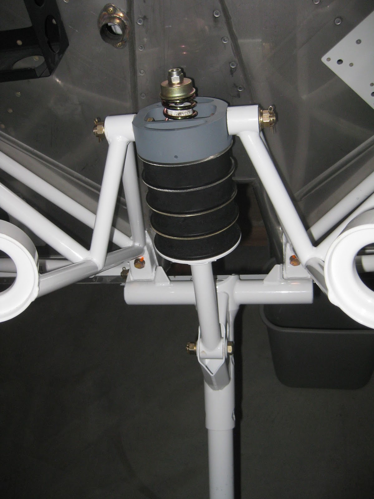
The engine mount was easily done solo in 30 minutes. I was even able to torque the lower four bolts, leaving the top two loose to accommodate the later riveting of the F-01471 Forward Top Skin.


The U-01406 Nose Gear Leg went in easily enough, after removal of requisite powder coating. I still need to verify the tightness of everything then bend the cotter pins down (it's worth noting that Van's Support stated to torque the MS21045-6 bolt, top of Figure 1 on page 40A-06, Step 6, to spec.). The only thing worthy of mention is that if you're doing this work solo, have something to keep the leg from rotating downwards prior to attaching the gear link assembly parts, otherwise the Nose Gear Leg will fall through the F-14132 Tunnel Angle on your firewall and make life miserable.

So just the placement of two gear legs took me an extremely frustrating 50 hours, 10 of which were with help, whose duration had me wanting to throw in the towel and go buy a flying Lancair with the money I don't have. With the information I learned through this process, I could have placed them myself in no more than 2 hours. It would be helpful if the plans were more specific (see my suggested approach below), especially given that the parts are almost assured not to fit on the first attempt.


Here is how I would attach the Main Gear Legs on my next build (this departs from plans slightly):
- Per plans, attach the Upper Gear Brace.
- Carefully and slowly slide the Main Gear Leg into position until it binds.
- Do not rock the Main Gear Leg or force it into position.
- Remove the Main Gear Leg and note the marring on its fore and/or aft surfaces where the binding occurred.
- Gently file down this area until the marring mark is removed.
- Repeat previous 3 steps until the Main Gear Leg can slide fully upwards into position.
- Mark where the powder coating needs to be removed so that the area on the Main Gear Leg where it contacts the Lower Gear Brace and Gear Attachment Bars are bare.
- Remove the Main Gear Leg and remove the identified powder coating.
- Attach the Gear Attachment Angle.
- Slide the Main Gear Leg back in to position.
- Shim as necessary and torque the bolt through the Main Gear Leg.
- Attach and torque down the Gear Attachment Angle.
- Lubricate all bolts prior to placement being careful not to get lubrication on the threads.
- If a bolt requires significant force to push through its hole, verify alignment rather than beating the bolt in.
- Do not spin bolts to torque their nuts.
- Crow's foot wrenches are ideal. I used ratcheting open-end wrenches until the nuts started tightening, then switched to a torque wrench, using a crow's foot when necessary.
- Adjust torque as required to account for any additional moment arm (it'll probably be near 5 in-lbs reduction for a medium sized wrench, so if you don't torque to max spec, you probably don't need to bother).
Man is this helping me do my gear legs. Van's shipped mine with the powdercoat already removed in the brace area but I had to remove a bit of steel fore and aft - pretty easy with the coarser scotchbrite wheel as opposed to a file (easy to take off very tiny bits and nice smooth edges).
ReplyDeleteAm very happy to hear the information was helpful! Build on my friend.
ReplyDeleteI would like to thank you very much for the pictures and your description how to do this
Delete