Showing posts with label Pitot-Static. Show all posts

03 November 2019

Pitot-Static: Steam gauge altimeter calibration

I have a Winter 7 FMS 523 altimeter as a steam gauge backup on my panel.


The altimeter is consistently off by 200'.  It turns out that adjusting an altimeter is relatively easy:  There is a small screw near the main adjusting knob.  One simply backs this out and then you can pull the main knob out to change the altitude without changing the value in the Kollsman window.

Below shows that small screw on my altimeter.  It was packed in grease (probably to mitigate it from falling out) but easily accessed with a jeweler's screwdriver.


13 November 2018

Pitot-Static: Changed static ports and associated plumbing

I decided to replace the rivet-based static ports with something more serviceable and that does not require sealing.  Van's has a solution for that.

Here it is, installed. 


Compare to this, the original installation, back on 12-Jul-14.


09 April 2017

Wings: Pitot static. Lines and wiring routed.

Quick set of pics to show how I solved the problem of my Dynon heated pitot/AOA line and wiring routing.  The challenge was that I chose to install the pitot tube in the bay just inboard of the aileron bellcrank.  This meant that the pushrod was in the way.  If I were to do this again, I would put the pitot outboard of the bellcrank

I used two push-to-connect elbow fittings from MettleAir: 1/4" OD to 1/8" NPT, model  MTLF1/4-N01.  This allows connection into the pitot/AOA tubes with minimal additional hardware (unlike my first design back in 2013) as only an AN816-3D nipple was necessary with the elbow fittings.

The two images below are from the same vantage point, with different lighting schemes, looking inboard from the bellcrank inspection hole.


This is looking outboard from the center inspection hole.


The wiring was negotiated to accommodate mounting the controller box on the center inspection cover.


Left pitot tube installed (I have dual pitots in my plane).


Read the entries in my AOA series:

27 September 2016

Pitot-static-AOA system routed in airframe

First, the diagram of what's needed for my panel design.


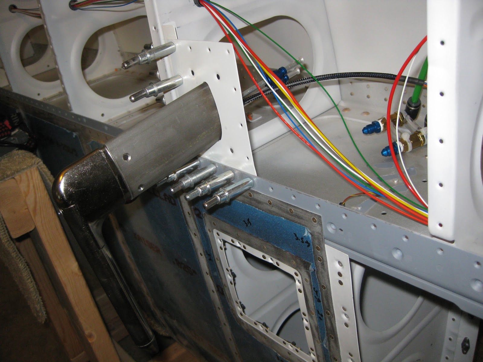
It turns out that the wire clips under the seats are not large enough to house the wiring to the wings and the pitot-AOA lines, in the case of the left wing.  So I had to drill through some of the seat ribs to route those lines.

I marked the route I wanted then used the pneumatic angle drill to start the holes with a #40 bit, then upsizing to a #30.


Then I used my electric hand drill with a right angle drill attachment and 1/4" drive unibit set to upsize each hole to their final 3/8" size so that a SB-374-4 snap bushing could fit.


The final routing for the left pitot (green) and AOA (blue) lines from the rear bulkhead to the wing root is shown below.


The air lines are from Coilhose Pneumatics NC0440, 11/64" I.D., 1/4" OD, 0.04 wall thickness.  I originally purchased these for my Dynon heated pitot/AOA from Avery Tools back on 22-Aug-13 under the SafeAir1 name, however it is now available for much cheaper from MSC Direct and other sources.

Also, the push-to-connect fittings are from MettleAir.  These are much less expensive than the SafeAir1 branded fittings available elsewhere.  I found the MettleAir fittings on Amazon.  They incorporate an NBR o-ring and stainless lock claws.  Each image below links to Amazon.
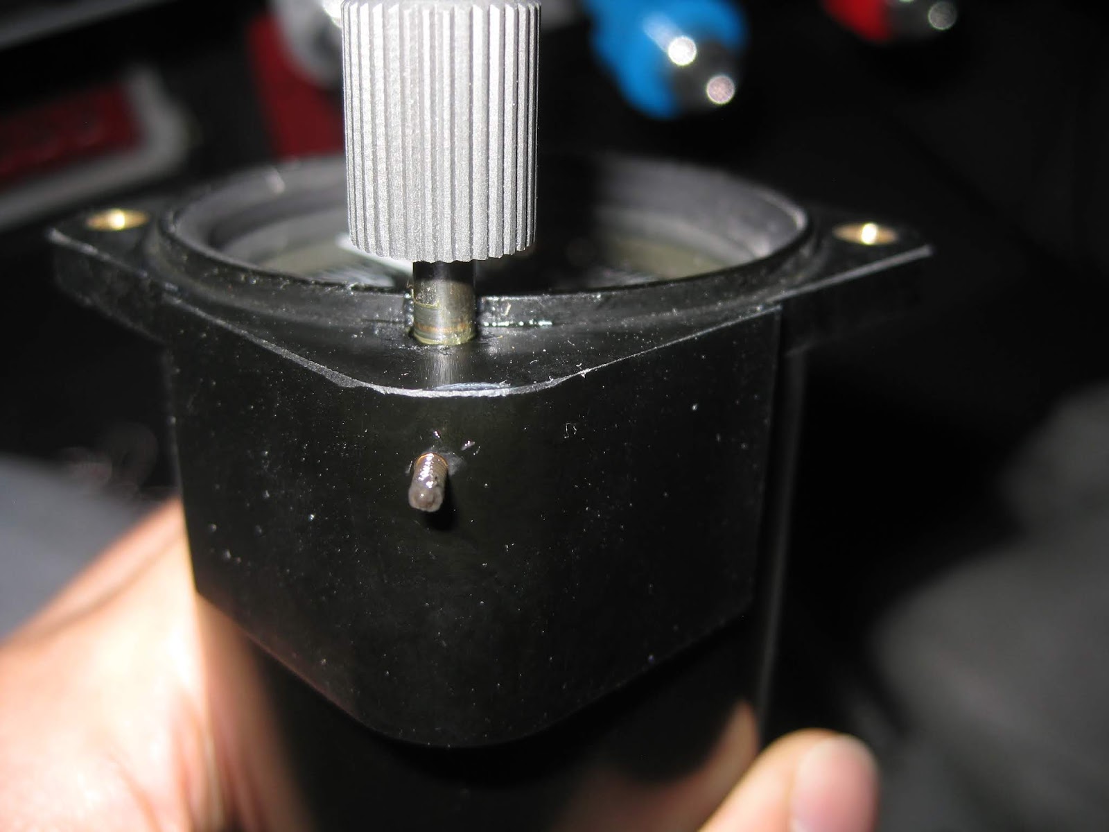
https://www.amazon.com/gp/product/B00S51JG4C/ https://www.amazon.com/gp/product/B00S51IHYM https://www.amazon.com/gp/product/B00S51LAVY https://www.amazon.com/gp/product/B00S511SAM

My TruTrak ADI2 requires a pitot connection.  Per my diagram above, it uses the right pitot so that it is independent of the EFIS' left pitot.  Below is that connection.  TruTrak specifies that the static connection remain unconnected in unpressurized aircraft.  So the other port on the block remains unused.


The GRT AHRS gets left pitot, AOA and static connections.  If you look closely, my lines come in at a slight angle to each port.  I was originally concerned about that.  However there are no apparent leaks even when shaking the lines.


The Winter 7 FMS 523 ASI and Winter 4 FGH 50 ALT both get static whilst the former additionally gets right pitot.  These instruments were added to provide an independent and non-electric means of airspeed and altitude indications.  The ASI, using the right pitot, provides a redundant indication should the left pitot get blocked.  You'll notice I didn't use red tubing into the winter ALT after the elbow.  For whatever reason, the barb on the pitot port was not beveled, so I just couldn't get the red tube on.  Yet the white tube was more malleable and accommodating to its fitment.


Here are images showing the tee'ing of the lines as they come up from the tunnel.  Left pitot and AOA tees (left), static tee (center) and right pitot tee (right).


The system appears to hold air for at least 5 minutes in all lines.  I will test it more formally later.

A later post will outline the tribulations of my wiring endeavor, some of the details of which are rather prominent in the images on this post.

14 August 2015

Avionics: Pitot-Static. Audible beeping tone with varying frequency.

A lift reserve indicator (LRI) is a differential pressure measurement device that provides an indication of how much lift is available to the pilot.  Whilst I'm not schooled in how it might be different from an angle of attack (AOA) indicator, to me they seem the same.  Here is a great tutorial on how to build one, which is half of what I plan to construct.


The different zones are calibrated to mean the following.

Red Lift available is not sufficient for level flight.
Upper boundary represents stall speed.
Yellow Bottom boundary is just enough to support level flight.
Remainder represents slow flight/final approach region.
Green Lift available exceeds what's necessary for level flight.

A 0-2 inH2O differential pressure gauge is used as the LRI.  The Dwyer Minihelic II 2-5002 Differential Pressure Gauge, Range 0-2.0"WC is one such gauge.  Its specs can be found here.  Should you prefer a horizontal or vertical implementation, the Manostar FR51HV/VV would fit your bill (my apologies, however I do not know where to procure either version).  The input to either is a standard AOA probe, fashioned by one's self or purchased.  I will be using my Dynon heated AOA pitot probe.

I also want to have an audible indication of my LRI status.  For that I will need a transducer which will convert pressure differential into a voltage.  Then I will need to take that voltage and convert it into sound for the pilot.  My understanding is that the F-4 Phantom had a similar setup to help pilots fly at the edge of the flight envelope (I assume other military aircraft have the same instrument).  Here is a description from the F-4 flight manual and an image of the indicator (click here and search for "AOA" to learn more about that instrument).

The transducer I will use is the Honeywell ASDXRRX001PDAA5, which is available from Digi-Key, Mouser and Newark, among others.  It converts +/- 5 inH2O to 5-95% of 0-5 V.  It has 0.091" male ports.  Tubing that would work might be this nylon 1/8" OD from Grainger.  One can also use the remaining "PT 1/8 CLR PLASTIC" tubing from from the empennage kit or directly from Van's.


The output from this differential pressure transducer can then feed a simple voltage-to-frequency converter when the voltage reaches a lower threshold.  Here is one such circuit example, based on the LM331 and another here.  Another example would be a simple VCO (voltage controlled oscillator).  When I complete the design, I'll post more.  However with GRT's recent addition of AOA, I may not need the circuit and will just keep the "steam" based LRI.

29 June 2014

Wings: Pitot static. Mast powder coated.

Nothing too exciting here.  My -9A friend graciously had my pitot mast powder coated.  Decided to go with a silver that matches the pitot tube well enough.  That should then match whatever color the plane gets painted.


Read the entries in my AOA series:

10 November 2013

Wings: Pitot-static. AOA/pitot doubler plate riveted in.

The left wing's AOA/pitot tube doubler has been riveted in.  I'm using the PBK-12 Gretz Aero bracket.  A full description of my setup can be found here and another outlining my dual pitot approach.  

First I had to calculate the proper rivet sizes.  There are four separate thicknesses to consider.  Below are the calculations.  I opted to round up in all cases.  The additional length required after passing through the pieces to be riveted is 1.5x the rivet diameter.  So 1.5*3/32=-0.141.


3/32” Rivet
Skin 0.025 0.025 0.025 0.025
Plate 0.040 0.040 0.040 0.040
Spar 0.063 0.063

L Bracket 0.025

0.025
Additional 0.141 0.141 0.141 0.141
Total Length 0.294 0.269 0.206 0.231
Size (in 1/16”) 4.698 4.298 3.290 3.690
Rounded Up 5 4.5 3.5 4
Rounded Down 4.5 4 3 3.5


One interesting observation is that the #8 screw holes on the skin didn't quite line up with the corresponding holes on the backing plate, despite all my rivet holes lining up from when I originally fitted and match drilled the pieces.  It suggests the pilot bit slightly walked when I drilled the #8 holes.  It's not too big a deal as the screws will compress everything together, however it's a less than desirable occurrence.  It means the dimples in the skin and backing plate don't align.  Below shows the gap between the skin and plate.


Read the entries in my AOA series:

24 October 2013

Wings: Pitot-static. Heated AOA/pitot wiring complete.

The Dynon heated AOA/pitot wiring has been added.


Clearly, I chose to mount the electronics box on the access panel.  I tried many different permutations of mounting it on the rib and I just didn't like how it would either 1) require additional mounting plates or 2) not be fully seated on the rib.  See examples here and here and on an RV-14 here and here.  The access panel approach solves all those problems plus gives easy access to the box.

I still haven't put the bottom skins on as I'm waiting to complete the autopilot roll servo fitting and landing light wiring.  You can also see part of the AOA/pitot mount cleco'd in on that image above.

Parts needed were:


Read the entries in my AOA series:

08 September 2013

Wings: Pitot-static. Dual pitot plumbing completed.

I decided to go the dual pitot route, with the Dynon heated on the left and the normal Van's tubing on the right.  The Dynon will feed the EFIS and the "raw" tubing one will feed a steam gauge for backup.  Later, during panel design, I might even rig up a set of valves so I can choose and/or share pitots between instrument sets.  For this setup, I had to drill another set of holes in the ribs to carry the pitot lines.

Parts needed for for the Dynon:
Parts needed for both.
I had to add some holes in the ribs.  The right wing needed a set for the pitot and the left wing needed a set for the AOA (the plans included holes for the pitot line on the left).  Wish I had thought of this before assembly.  It was relatively easy to drill the 7/16" holes on the outboard ribs, but given the density of the doubler ribs on the inboard side, some headwork was required to work this out since the drill is far too large:  I used a 1/4" socket extension and inserted the unibit between each rib (since the unibit's largest diameter hole is 1/2", you can't pass it through each rib).


And left side first...I pulled the pitot and AOA lines through the left wing after installing the fittings with the spacer (thanks to Ken for the idea).  Then I lined up the Dynon tube to determine how much of the lines to cut with the pipe cutter.  After cutting to the right lengths, the nuts and sleeves were placed and the lines were flared with the flaring tool.  Here are a few pics showing temporary placement.  You'll notice I swapped the AOA and pitot tubing locations for better fitment.  The reason why I wanted the elbow fittings was to keep the lines coming from the Dynon tube straight so future servicing and/or removal should be easier (Update 9-Apr-17:  I ultimately routed the airs lines as shown here).


For the curious, the little gray spots on the spar webbing are areas that were scratched during leading edge installation that I later sanded out and primed.  Also, the red and white wires that seem to curl off to the right are the Dynon pitot heater and status light wires I strung earlier.  They're just pushed out of the way for now.  You can also see the extra wires I added for my landing lights.  More on that in a later post.

I also decided to countersink the PBK-12 Gretz Aero bracket after match-drilling and tapping the holes in the probe.  Because the bracket surface is curved, I c'sunk by hand with a deburring bit, very slowly.


Off to the right side...A 7/16" hole was needed for the right wing pitot (following removal of the rivet that was originally there).  The plans call for this to be done on the left wing, of course.  But that's where the Dynon heated pitot will be.  What's interesting is how little leading edge skin remains on the aft side after that hole is drilled.  Prior to mounting the hardware, this will need to be primed.


Here's the right pitot hung with and without the cover.  I used the kit's clear tubing for the right side pitot to help differentiate it later at the panel.


You can see some Cherry Max rivets in a bag that I'll be using on the right inboard leading edge rib.  Update 5-Dec-15:  I did not use the Cherries.  The difficulty I had with setting these AD470 rivets was that the offset rivet set kept spinning in the gun.  I've since learned to use duct tape to prevent the set from spinning and to increase the air pressure to accommodate the set's flexion.


Read the entries in my AOA series: