Showing posts with label Fuselage (all). Show all posts

09 October 2017

Fuselage: Rudder and Brake Systems. Longer rudder cable links.

I have given away all of the extra sets I had.  If you need a set, download the CAD drawing (consider updating the spacing as I explain below) and buy the steel stock material.  Links to both are provided in this post.

When I push the left pedal forward (which of course simultaneously pulls the right pedal aft), the "ear" on the WD-655-R pedal frame contacts the horizontal tube of the WD-655-L pedal, preventing the rudder from hitting its left stop.  My pedals are in the forward-most position (closest to the firewall).  This happens even with the proper rudder travel.

Below illustrates where the contact occurs as the right pedal is pulled aft and the left pedal pushed forward.  You can see where the powder coating came off due to the contact.


It appears as though the CS-00015 Cable Links need to be just slightly longer so that the cable need not be pulled forward so far (page 33-12).  Or, alternatively, that the CS-00014 Rudder Cable needs to be slightly shorter.  The latter solution is not practical.  I consulted with Van's and they suggested fabricating longer Cable Links or reducing the rudder throw.  However, to accomplish the latter would excessively limit the throw, so I deemed it undesirable.


So I bought some inexpensive 0.05" 4130 steel stock (the same material and thickness that the kit's links are composed of) and whipped up new cable links in my CAD program (LibreCAD - free is good).  I added two additional holes in comparison to the original cable links, giving me 9 holes rather than seven.  I went ahead and dropped four full sets on there since the waterjet shop was going to charge me the shop minimum of $75 for the small job. 


Ultimately, the waterjet shop said they'd make as many as my material would permit.  That turned out to be 18 Cable Links, so 4.5 sets.  Below shows the links.  The top row are 14 links as they came from the shop (dirty, rusty and undersized holes).  The bottom row shows one of the kit's Cable Links, followed by two sets of the longer links after final drilling to #12, deburring, sanding and cleaning for painting.


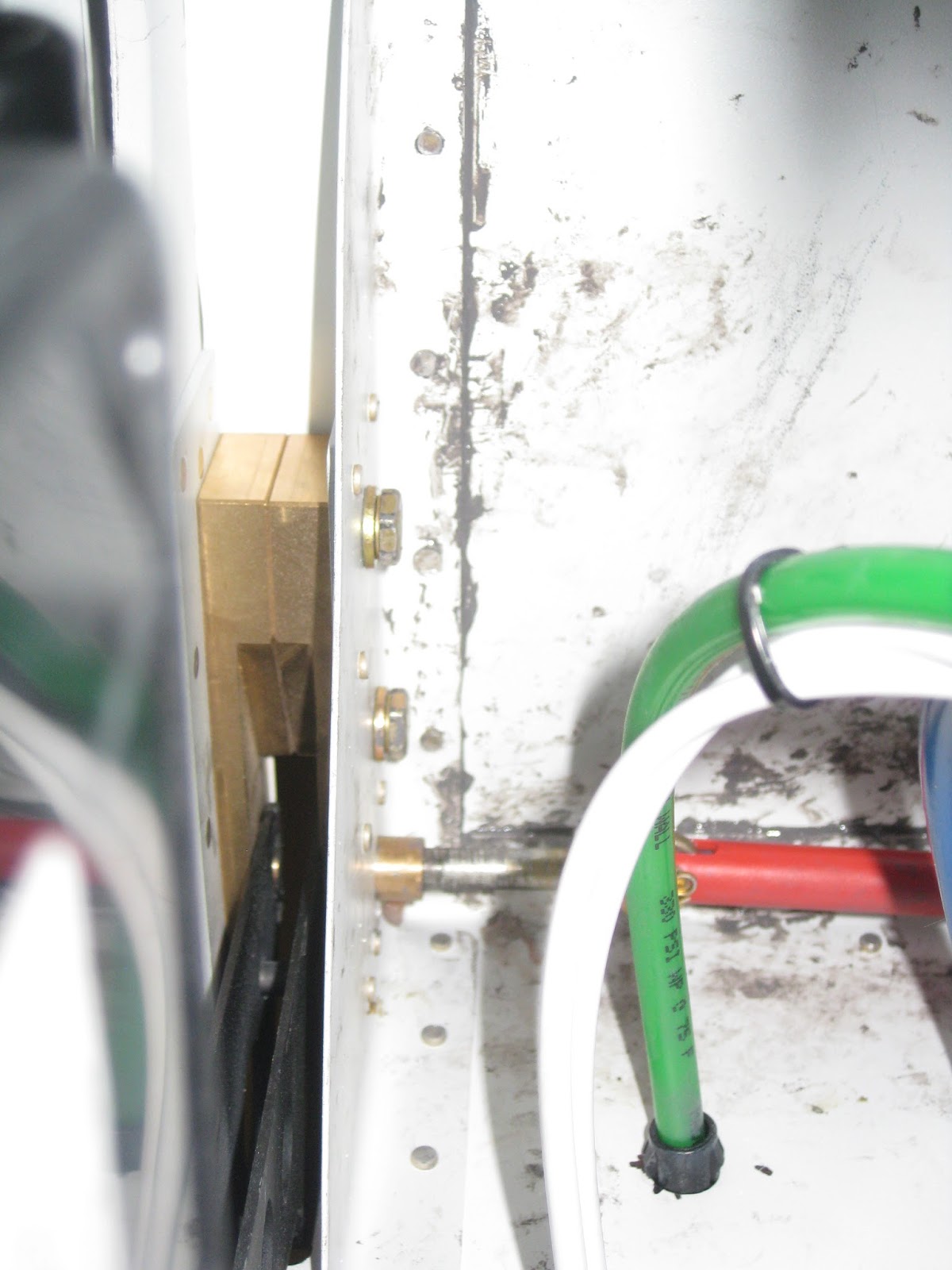
Installed, following painting.


If you need to fabricate your own, below are the final dimensions (ream to final size).  These line up very well with the original, shorter cable links.  Also, here is the dxf file with 16 links (the hole diameters are undersized by 1/64" and the width of the links are 0.04" wider to account for waterjet tolerance).
  • Holes are #12, so 0.189" diameter.
  • The first hole is centered 1/4" from the edge.
  • The second hole is center-to-center 0.75" from the first hole.
  • Subsequent holes are spaced 11/32" (0.34375") center-to-center.
    • I think the holes on the original parts are spaced 0.3445" center-to-center.  That would place exactly 1/4" from the hole edge to next hole's center.
  • The edges are half circles with a 0.25" radius, centered with the adjacent hole.
A picture probably expresses that much more clearly.

29 May 2017

Fuselage: Upper forward fuselage. Top skin riveted on.

Back in November 2015, when I mostly completed the upper forward fuselage section, I opted to not rivet on the F-01471 Forward Top Skin so that I had complete access to the area behind the subpanel during my wiring endeavors.  

Now that wiring is complete, it was time to put on the Forward Top Skin.  There are three complicating factors.  1)  The C-01440-L/R Canopy Hinge Bracket bolts make access for riveting difficult.  No joke:  We used chopsticks to keep the bucking bar aligned. 2) The skin needs to be entirely sealed with sealant.  Finally 3) it ain't fun being the guy with the bucking bar.

When cleco'ing the Forward Top Skin in place, I found that I could not get the holes into the longeron to line up properly.  Which is odd, because back in November of 2015, the F-01488-L/R Upper Engine Mount Brackets were match drilled into the skin whence the skin was cleco'd originally from the center to the sides.  However, I found that if I cleco'd the sides of Forward Top Skin first, I could get excellent alignment.


My poor friend drew the straw for holding the bucking bar.


Here we are, riveting away.  Sealant is applied to all flanges prior to cleco'ing the Forward Top Skin on.

 
On the Upper Engine Mount Brackets, the bolt holding the FF-01400 Dyna-1 Tri-Gear Engine Mount prevented good access to bucking the forward-upper-most rivet.  I didn't want to risk messing up this important area of the airframe.  So I checked with Van's if a CherryMax CR-3212-4-5 could be used rather than the AN426AD4-7 (which is what is done for the analogous rivet on the F-01489-L/R Lower Engine Mount Bracket).  They approved of the substitution.


Here are the Upper Engine Mount Bracket rivets from the outside, on the right side.


Here are the bucked rivets on the left and right mounts.  They are acceptable.


A few pictures showing the sealant results.  It got messy in there, but no worries:  No one will see it.


Then the flanges for the SkyBolt quarter turn fasteners were riveted in.  These were fitted back in December of 2016.


Next step is finishing up the sealant application.


It's important to fill with sealant all of the relief notches on the forward and aft edges.  When this cured, I painted it the interior color


Then I applied another layer of sealant because I didn't like how the first one came out.  I am please with how this finally came out.  What you're seeing below are the lower edges of the Forward Top Skin where it meets the F-01455 Sub Panel.


Here are shots showing the relief notches filled with sealant.  The rivet in the left picture was later replaced (in fact, it was this very picture that showed that the rivet was unacceptable).


All done (my friend is reworking the top cowl left side).

03 April 2017

Fuselage: Fwd Mid Fuselage Side Structure. Vents.

I had the pleasure of installing the side vents twice.  The first attempt, on 8-Mar-16, failed because the method I chose to clamp them was ill-conceived and gravity, the ultimate downer, caused them to slide down.

Preparing the vents for match drilling.  Not shown is the later scuffing and painting of the vents.  As can be seen, I returned the stock plastic eyeball vents and upgraded to the expensive aluminum ones on advice of a friend with an RV-9A who has experience with both.  Apparently the former leak whilst the latter do not.


Here is the foolish methodology for clamping the vents when adhering them.  Don't do this.


As is visible, the vents slid down overnight, adhering themselves in the wrong locations.


So I had to pull the vents off and scrape the sealant off both the airframe and vents.  That took exactly 4 hours of scraping.

More than a year later, on 7-Apr-17, I engaged in a second attempt at adhering the vents.  This time I used high strength, rare earth magnets to keep them in place whilst the sealant cured.


They came out pretty good. You can also see that I chose to paint them black to keep with the red/black accents in my interior.

Right side.


Left side.


If you look closely at the interior shots, you can see where I painted with a brush some of the silver paint to cover up the scuffed areas and the extraneous sealant.  Though those areas are obvious in the images due to the camera's flash, they aren't easily noticeable with one's eyes.

As a side note, the plans call for using silicone to adhere the vents.  I chose to use sealant.  And based on how exceedingly difficult it was to remove the vents when I originally placed them, I am entirely confident that they are staying put with sealant.

13 February 2016

Fuselage: Aileron and Elevator Systems. Control columns in.

This post is delayed due to my researching a good way to grind/sand the control stops.  The work in this post was mostly completed in November.

For the control columns, we're directed to line up the CS-00007-L/R bases to the CS-00008-L/R with a digital level, then use a "dab of superglue" to hold the parts for match drilling. 


After letting my dab cure for a day, as soon as I picked up the adhered assemblies, they separated.  So, I used the superglue completely around the joint between the parts and let that cure for day.  Let me assure you, those parts were now locked together.  Then, with generous Boelube usage, the match drilling went without a hitch (below)  Afterwards it was easy enough to break the superglue bond with a few light taps on one of my EAA Chapter 1000 benches.


For placing the CS-00004 stick link pushrod, a number of washers are required (left).  The inner ones are a challenge to place, as you can imagine.  A builder suggested I superglue them to the bearing on the pushrod (right).  Seemed like a great idea.  But as soon as a shearing force was applied during placement, the washers fell right off.  So that didn't quite work out for me.


Searching around, so as not to reinvent the wheel, yielded this little gem of an idea.  I was able to fashion that with some scrap (left).  And using this tool, the washers were placed with ease (right).


The next challenge was filing down the stops to meet the deflection criteria on page 36-13.


It's very challenging to reach the stops on the top and incredibly challenging to reach the ones on the bottom.  I bought a diamond riffler set to help...


...though at times using this gentle "grinder-on-a-stick" on my Dremel helped too.  The left image has the grinder oriented on the top stop, whilst the right on the bottom stop.  These demonstrative images were taken after I was done grinding the stops, hence why the control columns are in.


I also found it useful to have a small vanity mirror positioned below the bottom stop to help me stay on target with both the Dremel and the rifflers.


The sticks are in awaiting their control shafts/grips.


21 November 2015

Fuselage: Roll over structure. Completed.

The roll over structure construction is quite straight forward.  A lot of cleco'ing and match drilling is required, along with copious care to ensure parts are mated aligned and remain so.

The F-1231E Roll Bar Splice Plates are riveted on with the F-01431A-FL/FR Roll Bar Frames temporarily placed on the F-1231D Roll Bar Bases to lock the frames in place (below).  I was able to get the forward frames to easily align together with the bases and splice plate.  The aft frames, however, required significant prodding to achieve alignment.


The frames are then fully cleco'd with all of their requisite parts, so that match drilling can commence.  Here, every other cleco has been removed to support the match drilling process, later replaced with copper clecos (as an aside, I actually had to buy more copper clecos to complete this step).


The F-01431D window shims need to be countersunk for CS4-4 rivets (remember to use your 120° countersink).  Those shims aren't very thick, so without additional support, the holes would be hollowed out by the countersink pilot.  Thus, I chose to countersink the shims when they were cleco'd on the roll over structure.  Also, prideful rivets aren't desirable here, as the rear window rests on the shims.


The parts are then uncleco'd, deburred and taken out to pasture, where they are cleaned, acid etched, scuffed, cleaned again, then primed (I opted to use Napa 7220 rather than mix up a batch of two part epoxy primer for such a small job, though a few parts were already primed previously and are thus white rather than gray).  The parts are riveted together.


Some match drilling into the roll bar bases...


Not yet knowing what my exterior paint scheme is going to be, and realizing that once the rear window goes on, painting the roll over structure becomes difficult (and impossible for the upper arc underneath the window), I decided to paint it the same color as my interior.  I considered painting it black and even red, but decided that using the interior color would give me more options for the later, undefined, exterior paint scheme.

I had painted the F-01432A Roll Bar Brace red when I previously painted some other smaller parts red.  I painted the brace impulsively, not really giving much thought to how that would affect the options for the exterior scheme (so I guess I'm going with some red).  And, I thought it would create some unobtrusive eye candy if I were to paint the C-01432 Bushing Doubler and C-01433 Bushing Covers in some contrasting colors.  So the scheme should look like the below:


Following final riveting, the final product is as below.