Showing posts with label 13 Main Spar. Show all posts

08 May 2013

Wings: Flaps. Brackets riveted to ribs.

Section 15 is done!  Picked up an inexpensive torque wrench from Harbor Freight to complete the last page in Section 13, page 13-05 (bolting the aileron bellcrank brackets).  I generally avoid Harbor as a source of tools since it seems like many things there are sub-par, but the feedback on the 'net was quite positive about this wrench.

Snap bushings are installed on the ribs.  Turns out I put in an extra 1/2" hole in rib #9 (from inboard) on the right side.  No big deal.

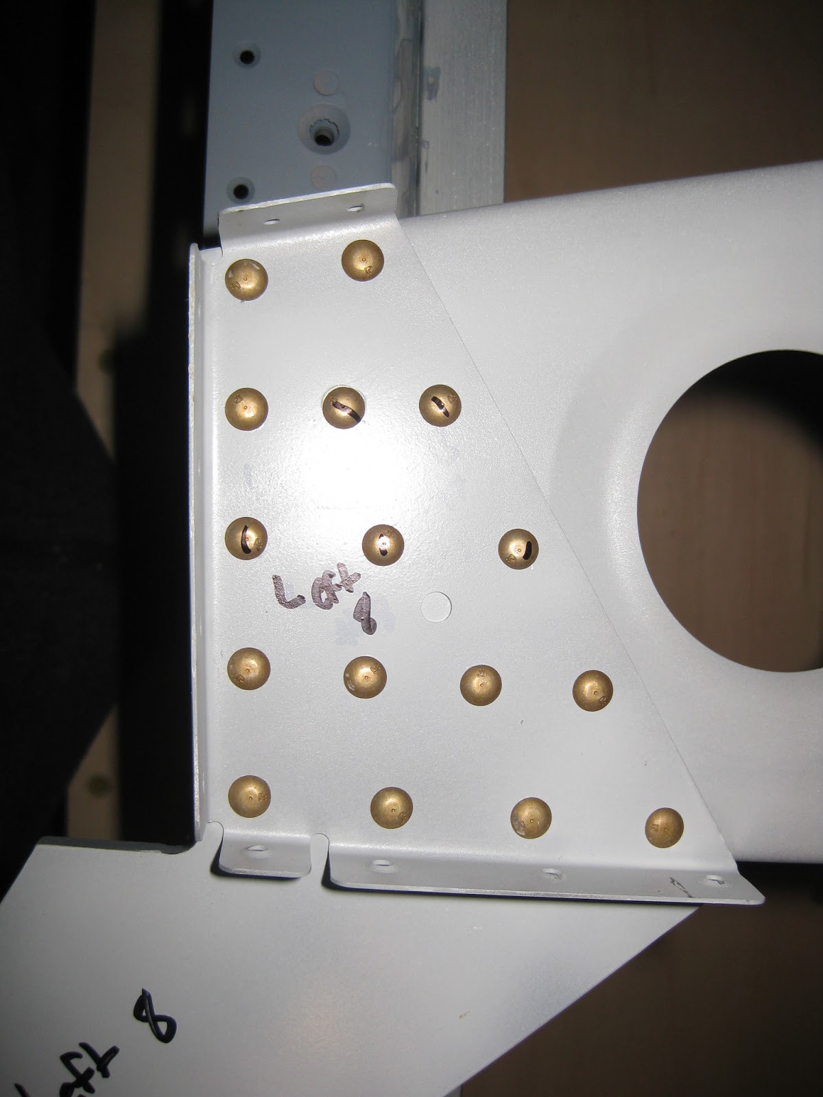
Each of the 4 flap brackets and their doublers are riveted to the associated ribs (#3 and #8).  I was able to squeeze five of them (the ones with the lines on their heads).  The rest had to be banged out with the 2x gun.  I used 90 psi on these -4 rivets.

This is the #8 rib on the left side.  You can see the Stewart System's EkoPoxy/EkoPrime.  It appears to hold up well.


25 April 2013

Wings: Main spar. Nutplates

I put in all of the nutplates called for in Section 13.  I used clamps to hold them in position then used the squeezer on every rivet I possibly could. 


Twice the squeezer caught the throat of the nutplate (image below), but the damage was so slight, I deemed it not worth correcting.


Here's one case where I wasn't being careful and riveted a nutplate 180 degrees out of alignment.  I just drilled out the rivets and replaced it.


Left spar with all flange nutplates installed.


Here are the factory and shop ends of the rivets holding a spar doubler plate on the right spar (before I banged on the rivets a second time).  I used masking tape to hold the rivets in prior to banging them.  Turns out that the cupped set stays in place easier that way (I learned that unintentionally).  But, one rivet got a little smiley.  According to MIL-STD-403C, page 10, "5.2.7.5 Marring of the manufactured head. A cut or ring caused by the riveting equipment used shall be acceptable on non-flush rivets providing the depth of the cut is not greater than one-fourth of the head height."  So, I'm okay with that.  I would probably make things worse trying to drill out a AN470AD4-6 rivet anyway.  The 2x gun takes about 60 psi to bang these guys in.


Interesting stress lines around the base of the aluminum on the shop end.  Turns out this is the anodized layer.


And then I went over those rivets a second time to square up the shop ends.  When I did that, I had removed the masking tape, thus I introduced smiles not just on the rivets, but the spar itself!  No bueno.


Took a lot of time to sand those out with 400 grit, shine it up with 600 grit, clean it then spot prime with Napa 7220.


Here are the fuel tank nutplates ready for riveting on the root of the spar.  These were difficult for me to rivet.  In fact, I had to drill out four since I set their rivets with the nutplate not flush.  You can see the primer I put down over the rivets that had smileys near them on the spar.  That was necessary after I sanded out the spar nicks.


Then the countersinking on the fuel tank nut plates.  These have to be deep to accept the fuel tank attach screws (AN509-8R8) and dimpled fuel tank skin.  I used the digital calipers to make sure I was in spec as called for in the plans.  I was 0.36" OD and 0"21 ID, exactly one hundredth of an inch below the max spec.  Whew!  The test fit looked good.  Following this, it was a another round of spot priming.  I wish the rivets holding the nutplate sat a little lower though.  They are barely beyond flush.


And finally (no pics for this), I used the wrong nutplate on the fuel tank nutplates out on the tip of the spars.  I used K1000-8D instead of K1000-3.  I must have seen the 3 on the plans as an 8.  Though the two parts are close in size, they aren't quite the same.  I'm glad I noticed they looked different (even though it was after riveting all 8 in) since now is the time to fix it.  They had to be drilled out and the countersunk holes primed again.  So, turns out I'm getting quite good at drilling out rivets.  The good people at Van's parts line are going to recognize my voice soon.

23 April 2013

Wings: Main spar. Countersinking and spot priming.

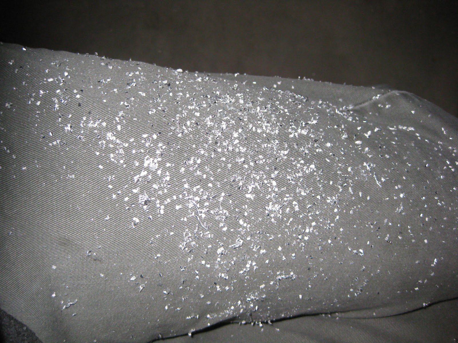
Lots of countersinking today.  Did all of the #40 holes in the spar as called for.  Leaves quite a mess.  Right picture is my pant leg!  I went 3 clicks further on the skin holes and added a little pressure (*note, Van's suggests 7 clicks). This should help the skins lie flush in the countersink.


Here are all the shiny new countersunk holes.


The plans call for the nutplates to be used as guides for countersinking their screw holes in the spar.  Many other builders use a piece of scrap, match drill it, then use that as their guide.  I decided to use that technique on the #40 holes only, using the nutplates for the #30 holes and repriming as appropriate.


Instead of spot priming, since it would take so long, I used Napa 7220 and just ran it down the flanges, using cardboard to prevent overspray.  Here's a shot of the right wing's lower flange.  I had to sand out the few scratches I created with the drill bit, prior to priming.

   
And a pretty shot of a primed, countersunk hole. 


Oh, and don't forget the #40 holes on the tip of the spar.  Keep in mind that those nutplates are attached to the aft portion of the spar, so you need to countersink on the forward part, not the aft!  Don't countersink the screwholes on these!  This was a mistake on my part as I misunderstood the plans.

13 April 2013

Wings: Main spar. Left spar defect?

Found these shavings compressed under some rivets on the left spar, near the root.  A replacement spar would surely slow down the build!


I called Van's and spoke to Scott on the 15th.   After checking with the folks who build the spars internally, they said sometimes the shavings don't get cleared out of the hole.  Scott said that if the gap between the rivet heads and spar is <0.005", then it's in spec.  I checked with a feeler gauge and according to that threshold, it's okay.

Wings: Main spar. J-stiffener.

Today was the first day of building.  The plans call for cutting up some J-stiffener and aligning them to the spar flanges to match drill them.  The Dremel worked great for cutting and the Scotch-Brite smoothed the edges.

First, clamp on the J-stiffener, making sure they rise 1/16" above the flange edge.


Match drill and cleco as you go, checking that the 1/16" is consistent.  On the bottom flange, there are holes you're not supposed to match drill.  I marked those off with a marker and kept the clamps there to avoid a mistake.


But, in true form, why not make a mistake on your first build day?  Below is the tip of the left spar.  You can see the J-stiffener placed up against the upper flange with a bit of a shadow underneath it to indicate that the J-stiffener is placed above the spar body so that it rises 1/16" above the flange.  Now, the text specifically says that the J-stiffener should be flush with the edge of the flange.  I decided that meant it should be flush with the edge of that piece with a rectangular hole near the bottom flange.  After all, that's what the picture looks like.  Well, turns out the perspective of the drawing is cause for confusion.  Too bad I didn't realize it until after I cut up the J-stiffener and completed match drilling the entire left spar's J-stiffener.  I now need to get some more J-stiffener from Van's.


So, basically, I did what was on the left, rather than the right.