14 November 2018

Maintenance: First annual condition inspection.

With 87.5 hours on the airframe following eleven months from the first flight, the first annual inspection was completed over the course of four days.  For the occasion I created a detailed checklist (using Tim Olson's N14YT checklist as a starting point).  My inspection checklist can be found below and on my page with my POH, flight checklist and flight test cards.  Be sure to customize the checklist to your own aircraft, should you choose to use it.

There were no findings of particular concern.   Here are the findings of interest:
  • The oil filler neck was loose.  The safety wire prevented it from working completely out.
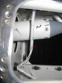
  • The fuel injectors showed stains from leaking fuel.  An investigation into the cause revealed that this is normal because the injectors take in ambient air to atomize the fuel (if air can go in, it can go out).  Image of injector #2.  Fuel stains visible.


  • The FF-00076 Sniffle Line Bracket continues to break (as first identified during an oil change).  A closer inspection shows that it simply melted (pure Al melts at 1,221 °F which is below the 1,500+ °F EGT) as shown in right image.


    I replaced it with a steel bracket which I fabricated from 4130 stock.

  • Brake pads appeared okay at 87.5 hours and 89 landings.


  • Apparently I neglected to grease the nosewheel bearings when I installed the wheels back in Feb-16! However, remarkably there was no indication of wear of any kind.  I'll take that as evidence of excellent technique in keeping the nosewheel up as long as possible on takeoff and landing. :)
  • The nosewheel pull out force was at 12 pounds (per page 40A-07, it is supposed to be 26 pounds, as I set it back in Feb-16).  I have never experienced shimmy.  Upon greasing the nose wheel fork, I could only get either 17 or 42 pounds of breakout force (due to cotter pin alignment).  I settled for 17 given that I had no shimmy at 12.  I don't recall, nor did I document, which grease I originally used during construction.   For this round, I used Aeroshell #6.  For the next round, I'll use a thicker grease.
  • The spark plugs looked reasonable for the hours imposed on them.

     
  • Added Spi Wrap to the elevator trim wire in the empennage and coming out of the trim motor.


  • The cylinders indicated the honing is still intact, so they are not glazed.  Cylinder #3 shown below.


  • Timing remains at 25° though the engine data plate specifies 20°.


Maintenance: SB 18-09-17 Aft bottom skin cracking.

Van's released SB 18-09-17 to address some cases of the aft fuse bottom skin cracking (examples of the cracks in flying aircraft can be found here and here). Following inspection of my airframe, I found no evidence of cracks.  However, I chose to install the stiffeners as described in the service bulletin.  The process took less than an hour with two people: One in the empennage and other underneath.
  
Here are the parts associated with the service bulletin.


Because the F-14148A Skin Doubler (the diamond) is affixed to the exterior of the dimpled F-01478 Bottom Skin, the dimples would remain unfilled and preserve voids under the six rivets which attach the Skin Doubler. So I chose to create fillers for the dimples by using drilled out rivet heads for the purpose.  Thus, I drilled out about 25 rivets on scrap to make sure I could obtain 6 rivets with well-centered holes.  I then sanded them smooth.  These six fillers were cleco'd into place on the Skin Doubler prior to cleco'ing on the skin (after all, we're working upside down here!), as shown below.


Removing the F-01406F Baggage Bulkhead Corrugration, placing boards and towels in the baggage area and a blanket in the tail, it was trivial to access the area required to install the stiffeners. 


A 12 inch #30 drill bit was used to match drill the bottom holes in each of the F-14147 Stiffener Clips.  There was adequate space available to squeeze the AN470AD4-4 universal rivets with my longeron yoke.   Tungsten bucking bars were used to buck the AN426AD3-x rivets.  It's worth noting that I increased the length of each AD3 size rivets by 0.5 as compared to what the SB calls out.

Following drilling through the F-01408-L/R Side Frames to attach the F-14147 Stiffener Clips.


Shop heads of the rivets, on the aft side of Side Frames, holding the Stiffener Clips.


Forward side of the Side Frames showing forward interior stiffeners in place.


Aft side of Side Frames showing single aft interior stiffener in place.


Exterior views of diamond Skin Doubler.  I need to clean up the area with acetone as I chose to prime the associated surfaces.


13 November 2018

Avionics: Minor change in electrical bus topology.

Minor change in my electrical bus topology.  First, a functional explanation of my three buses is in order:

  • Master:  Critical devices for flight such as lights, electric fuel pump, flaps, trim, ELT, alternator field that can also remain powered during engine start.  This bus should always remain on in flight.
  • Avionics 1:  Critical flight instruments such as left side EFIS, AHRS, GTR-200 transceiver, transponder, backup AI and low fuel level indicator.   This bus can be shut off only in VFR flight.
  • Avionics 2: Less critical instruments and devices to include right side EFIS, GTN-650 navigator, capactive fuel indicator, autopilot, GMA-245 intercom and ship's power LEMO.  This bus can be turned off any time to reduce energy demand (it should remain on in IFR to stay legal).
 
With that out-of-the-way, when I installed the canopy camera power, I used the "unassigned" fuse position that was on the Avionics 1 bus.  However, there is no need for the cameras to be on Avionics 1.  And, back when I designed my bus topology, I decided to put the GMA-240 (now a 245) on Avionics 2.  However, I should have kept the intercom on Avionics 1 so I can keep Avionics 2 off (primarily during taxi) and still hear my passenger.  So I decided to swap the two positions:  Intercom and canopy camera.  This required a lot of contorting, cutting of wire ties and losening of screws.  Here is the back side of my fuse block, which I designed (you can learn more about what I did here).  I had to remove a wire from the left and center rows and swap them.


Below is my new fuse legend.


I wish I had put the LEMO power on Avionics 1 so I can maintain power to the headsets with Avionics 2 off.  It isn't practical to change that now and the LEMO versions of my headsets understandably are not provisioned for batteries.

Pitot-Static: Changed static ports and associated plumbing

I decided to replace the rivet-based static ports with something more serviceable and that does not require sealing.  Van's has a solution for that.

Here it is, installed. 


Compare to this, the original installation, back on 12-Jul-14.


12 November 2018

Maintenance: Wing jack.

First use of my new jack.  I obtained the Alpha Aviation model 326 jack.  It has a 26-43 inch effective range, representing a 17 inch ram travel.   I coupled that with Bogert Aviation's RV jack pads.  Together, they worked great!


The jack:

The jack pad:

In use on an RV-10 (with a different jack):


04 November 2018

Avionics: Installed Kanardia Horis 57.

On 12-Sep-18, I received my Kanardia Horis 57.  It is to replace my TruTrak ADI2 on my panel.  The ADI2 is a solid instrument, however I like the additional information provided by the Horis.  It came to $1,040 plus $70 shipping minus $64 for exclusion of GPS antenna (can use the one from my ADI2) and remuneration for potential import fees.


It's a very capable device.  The following are just some examples, rather than a complete list:
  • Attitude 
    • Roll, pitch
  • Airspeed
    • IAS and TAS
  • Vertical speed
  • Altitude
  • OAT
  • Altimeter setting
  • G meter
  • Heading rate (1 minute and 30 second turn)
  • Tracking course
    • True or magnetic (with optional magnetometer)
    • Includes additional separate directional indicator function
  • Wind speed (with optional magnetometer)
I installed it on 4-Nov-18.  I placed the OAT sensor on the right wing on the inboard inspection plate (I didn't want to drill into the wing skin) and ran the cable through the upper aft bushings, under the right seat pan, up the tunnel and over to the instrument.


For reference, here is the OAT sensor pinout diagram.  It uses a 4C4P RJ-10 (also known as RJ-9 and RJ-22) connector.  I had to lop it off and replace it in order to negotiate the cable through the airframe.  I also had to buy a new crimper for the little connector.


Here is the rear of the instrument as installed.  The Horis uses 5 mm ID connections.  So I snagged some 8 mm OD, 5 mm ID nylon tubing and 5/16" to 1/4" couplings (5/16" is 7.9375 mm) to connect to my 1/4" OD pitot static system tubing.


Here it is in flight.  I need to calibrate the altitude as it's about 300 feet off.


03 November 2018

Avionics: Center console USB power socket change.

I decided to replace my center console dual USB power plug only because I found this neat one


Not only does it support QC3.0 (3A per port for compatible devices) and has a snazzy red anodized aluminum body (to match my red accented interior), it also has a cool voltmeter on it.  So far, it has not caused hash on the GTR-200 transceiver like my original USB power socket did.

Here it is installed in the airfame.  It did require me to drill out the hole in the F-14123 Power Outlet Bracket to 1.125".  That hole is now round and no longer has the flat "locking" sides.