29 November 2019

Maintenance: Fuel boost pump leak.

The first flight following my second annual was a ~200 NM roundttrip to have a "$100 salad" with a friend.  The plane was returned to the hangar following an issue-free flight.  Upon going to the hangar four days later, when I opened my canopy, I was greeted with a strong odor of avgas.  Clearly, there would be no flying that day.

Knowing that the only part of the fuel system that was touched during the annual was around the filter (to remove, inspect and replace the latter), I immediately removed the F-01452 Aft Tunnel Cover to inspect the area.  Fuel stains were located around the airframe's lower F-14108A Fuel Pump Bracket yet not the upper F-14108B Fuel Pump Bracket (see below diagram from Figure 31-11, brackets in red). 


Here is an image following removal of the pump and filter.  You can see the fuel staining on the lower Fuel Pump Bracket.


There was no staining near or on the boost pump's output side (thus the output fuel line remained sealed to the pump).  Additionally, no fuel staining was noted at the joint between the filter and pump or anywhere on the filter body, confirming that the leak was not due to the filter as that seal remained intact too.  Fuel stains were concentrated at the joint between the pump's segments at the lower-most, fuel input side (the pump is segmented, composed of three parts).

So what happened?  It is my hypothesis that when the fuel filter was reinstalled and joined to the pump (using standard NPT torquing guidance of "thread with fingers until resistance then 1.5 turns more" - see Section 5.27), the seal failed at the segment described above (drawn as a blue arc in the top-most plan-view image).

It appears that this same leak has happened to at least two other people.  I neglected to take a picture of the staining on my pump, but the pictures below indicate the same area of leakage.  Both images are from the thread referred to previously.


Upon contacting Andair, they requested that I send the pump back to them in England for complementary repair.  When received, they reported to me that they pressurized the pump and could not find the leak and requested more information about the location of the leak.  The following day they reported that the leak was found (no information given on what was done differently the second time around).  They said that they "replaced the pump body with the latest iteration (now machined as one part instead of three) and also replaced the pumps (sic) inner rotors to the latest spec and a new ESC."  So this new-ish pump should not be subject to the same leakage problem as the original.  I don't know what advantages the new rotors or an "ESC" (electronic speed control?) give me.

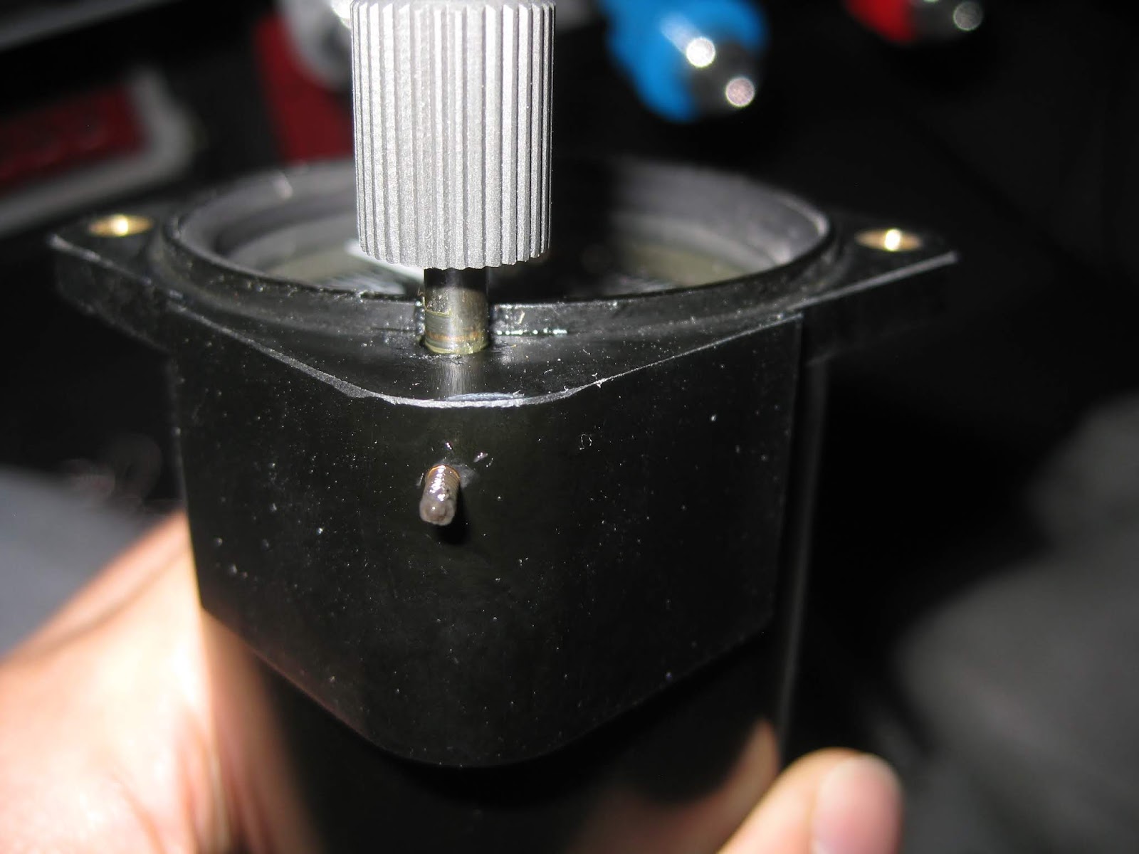
Here are images of the new pump with the single machined body.  It appears to me to be composed of two pieces with the fittings attached via hex screws.  The joint where it leaked before remains on the new pump body.


The new pump makes the same noise as the old one however its wires are now Tefzel.

11 November 2019

Maintenance: Second annual condition inspection.

The second annual was completed at 165 hours.  My inspection checklist can be found below and on my page with my POH, flight checklist and flight test cards.  Be sure to customize the checklist to your own aircraft, should you choose to use it.

Here is the aircraft with everything removed prior to the start of the inspection.


There were no findings of particular concern.   Here are the findings of interest:
  • The left brake pads showed that they had quite a few more hours remaining.  However, the right brake pads warranted replacement.  This is either due to my overuse of the right brake or that it drags.  I will monitor for both.
    • Right brake pads.
    • One of the left brake pads (forgot to take picture of the other).
    • What a new pad looks like.
  • The fuel filter trapped some material and collected water (the filter has a local low point) and subsequently rusted itself.  The source of the water is uncertain and I will take to sumping the tanks more frequently.  The rust was on the input side of the filter, however the filter has been replaced with a new one.  Below, on the left image you can see the rust (and other detritus) and on the right image, which is the filter casing, the rust is in the upper left (which is the low point of the filter).
  • Here I demonstrate the location of the water collection in the filter.  The blue area is the local low point where water aggregated (image modified from Figure 2, page 31-09).
  • My belly is an oil slick.  See inflight picture here.  This oil has been sucked in to the area underneath the baggage floor.  I will be installing an oil separator later.  Below shows the F-01446 Baggage Floor Cover removed.  You can see how the oil has been sucked in at the lap joint between the Aft Fuse (F-01478) and Fwd Fuse (F-01484) skins
  • As expected, the outside of the tires wear more than the insides (with the left wearing more than the right).  I removed the wheels from the hubs and flipped them to get another 165 hours out of them.  Left and right wheels shown below, respectively, prior to flipping the tires on their respective wheels.  It's worth noting that I shimmed the right gear leg to leave me with toe-in 0.07° on the right and 0.1° on the left.
  • The hat switch on my Tosten CS-8 stick on the left side no longer functions towards the right.  I verified it is not a wiring issue, so it's the switch that failed (my wiring writeup is here).  Unfortunately, the warranty on the product is quite short (90 days after A/W certificate).  It's not a problem for me since I don't have aileron trim (with properly balanced fuel, it hasn't been necessary).
  • I finally accurately calibrated my optical low level fuel sensors.  I really did a poor job on locating them.  I did not properly factor in the wing dihedral.  The sensors trip at 0.64 gallons on the left tank and 0.84 gallons on the right tank.  They are last resort, emergency annunciators, so with proper fuel management, they should never go off.  But if one does, it simply indicates that I must switch to the other tank very soon, and pending that tank's available volume, decide to continue flight or divert for fuel.
Going back to the brakes, I purchased a Rapco brake rivet tool to make the removal and re-insallation of brake pads relatively easy.


Greasing the wheel bearings was quite simple.  I used avgas (!) to degrease the bearings then used this "handy bearing packer" to repack the bearings.  Below you can see the advantage of degreasing prior to regreasing.


I also lengthened the F-14127 Flap Position Pushrod by about 5 mm.  This was necessary since the sensor's resistance reaches its maximum prior to its arm reaching full extension.  Thus, my EFIS' flap indicator would reach "fully extended" about 3 seconds prior to the flaps being fully down.  Lengthening the sensor pushrod kept the arm's travel without the bounds of where the latter's resistance would change.  In the picture below, the bottom rod was fabricated to plans-specified length.  The top rod is the length that worked best for me.  The rod I used was K&S Round Rod, 1/16" diameter, 12" length, stock number 87131.


The engine compression checks out.  All four cylinders are 80/80.  Next time I'll try testing at a higher pressure.  Below shows one of the cylinders, illustrating the intact cross hatching, using my cheapo borescope (the camera's angle mirrors are worthless as the camera continues to focus beyond them).


The plugs looked fine. Below I show when they were removed, prior to cleaning and gapping with my servicing kit.


Until next year!


10 November 2019

Modification: Increasing roll servo leverage.

At high speeds, the control force on the ailerons is significant.  My GRT high-torque roll servo just can't articulate the aileron pushrods without slipping its clutch when flying at speeds above around 140 KIAS.  I had already moved the servo control arm closest to the servo arm pivot point, as shown below from GRT's autopilot installation manual.


With that option exhausted, I needed to increase the mechanical advantage to the roll servo.  Below is what my install looks like now, when the motor is overwhelmed by the control forces at high speed.  You can see the servo pushrod is at the "min throw/max torque" position.  And it's connected to the bellcrank one inch below the aileron pushrod pivot point (as accommodated by the bellcrank design).


Below is what I planned to do.  I wanted to make a new bracket (grey) that moved the attachment point of the servo pushrod (yellow) further from the bellcrank pivot point.  This would give the servo greater mechanical advantage (since large movements of the roll servo would translate to smaller movements of the aileron).


So, I hopped into LibreCAD to fashion some brackets with varying lengths.
  • My plan was to make these brackets out of 0.125" 4130 steel stock.  I suspect  that's thicker than it needs considering the bellcrank material is much thinner.  
  • The spacing between the aileron pushod rod end bearing and the nutplate on the bellcrank for the servo pushrod's original position is exactly 1". 
  • I wanted to use a nutplate to attach the distal rod end bearing of the servo pushrod so I didn't have to fuss accessing a nut on the backside of the bracket in the limited space afforded by the inspection panel.
  • The bracket width of 1.2" was dictated by the mil-spec edge distance requirements associated with nutplate rivets (I later found out that this was too thick and would bind on the aileron pushrod).


This would also mean I would have to lengthen the servo pushrod from 3.25" to 4".  So I bought some tubing and used this method to drill holes in the center (since I don't have a lathe or mill) and threaded it.

Here's my collection of brackets ready to go.  In retrospect, I gave myself too many length options.


Here's a bracket (second from the left above) attached.  The geometry of the pushrod didn't work out as the servo arm's angle exceed 30° of travel (causing a potential over-center instance and thus jamming the roll control).  No adjustment of pushrod lengths, across the four pushrods I had, would yield an acceptable geometry. 


I then made this temporary, not flight-worthy, bracket next.  The pushrod geometry with this bracket also did not yield something workable.


Next, I fashioned a new servo arm that has a hole slightly lower than the one on the stock arm.  Below is two of those exploratory, not flight-worthy, servo arms.  The large hole bolted to the servo.  The next hole goes to the shear screw.  The next hole(s) are locations for the pushrod.


As the pair of pictures below show, the servo arm with even "more torque, less throw" also did not have a workable geometry.


So at this point, I have no solution to the issue.  GRT has already checked out the servo.  They are checking with their software group to see what else they can do, yet I don't expect to hear back from them.  I remain of the sentiment that the servo lacks sufficient torque for the aircraft and that's the way it shall be.

06 November 2019

Interior: Poor man's seat warmers

It's winter time.  It's cold.  And so are my buns.  So, I snagged some "cheap" heated seat pads that plug in to a USB port.


Of course, that won't work in an airplane with narrow seats and a crotch strap.  So I removed the heating pads and placed them on my plane's seat.  I only need them on for a few minutes, then I'm good to go.  I will probably make a fabric pocket to place them in.  The pads plug in to my console USB socket.

Update 21-Jul-20:  When I got my interior rounded out, I had little covers made for these heating elements.


03 November 2019

Pitot-Static: Steam gauge altimeter calibration

I have a Winter 7 FMS 523 altimeter as a steam gauge backup on my panel.


The altimeter is consistently off by 200'.  It turns out that adjusting an altimeter is relatively easy:  There is a small screw near the main adjusting knob.  One simply backs this out and then you can pull the main knob out to change the altitude without changing the value in the Kollsman window.

Below shows that small screw on my altimeter.  It was packed in grease (probably to mitigate it from falling out) but easily accessed with a jeweler's screwdriver.