20 January 2015

Fuselage: Forward mid fuselage bulkheads. Bearing bracket assembly miscut.

As I was assembling the right bearing bracket assembly, I saw that the F-01450-L bracket (top bracket in images below) didn't have its aft edge properly cut.  You can see below that it doesn't match the -R part when cleco'd together.  This is an important assembly as it defines the control column travel limits, as seen below from page 36-13.


Van's said "It is fine.  It would make no difference, if you get a new/another one."  So they opted not to replace the part for me.  Whilst they may be right that it wouldn't matter, I am not comfortable with the defective -L part at such a critical location in the aircraft, so I shelled out the $8.79, shipped, for the replacement.

This is what well-cut parts should look like.  This is the right side bearing bracket assembly after replacement.


Note:  DO NOT use a #12 bit when a #19 is called for when match drilling the bearing bracket assembly to the cover rib.  I got to redo the right assembly for a third time!  Based on advice from a fellow builder, I now have a set of drill guides to verify I have the right bit in the future.

18 January 2015

Fuselage: Mid fuse lower structure. Seat ribs to skin.

First the rib and bulkheads frame is set up.


Then the skin is tacked on with clecos (left).  I used two baggage ribs to prevent the skin from flopping over.  Following four hours of help from a gracious friend, the seat ribs are on (right).


Next comes the baggage ribs.  Each one gets riveted to the bulkhead and/or adjoining seat ribs.  These AD4 rivets are difficult to reach.


For that, it was time to bring out my double offset rivet set.  This thing can be evil.  If it isn't restrained, it will rotate and wreak havoc on the manufactured head, endowing you with a rivet looking back at you with its big toothy smile.  So I secured it with some duct tape (does anyone actually use that stuff on ducts?). I managed to buck every rib-to-bulkhead rivet solo with judicious use of limb and rivet gun positioning.


In a few cases, I had to get creative to offer myself access to the rivets.


Now it awaits a bucking partner to rivet the baggage ribs to the skin.


Fuselage: Mid fuselage lower stucture. Idler bracket bearing.

The idler bracket bearing assembly requires the VA-146 bearing to be cut (page 26-09 shown below).


It's not easy making a straight cut on something round.  So I match drilled two holes into a block of wood so I could cleco the bearing to something solid.


I ended up doing an involuntary trial run on this step.  On my first attempt, I managed to cut the bearing too short (left).  The second attempt was successful (right).  Replacement VA-146s are $23.  Yippee.  I'm pretty sure I'm Vans' best customer (see the cost of replacements on the right column of the blog).


Incidentally, I was curious why the part is called an "idler bracket" since it doesn't seem like it helps hold anything that is idling.  Turns out the term is used to describe the pivoting support for a steering linkage.  In this case, that would be the up/down "steering" of the elevators.

17 January 2015

Fuselage: Multiple sections. Priming.

The weather finally turned, the air warmed and the snow melted.  This meant I could wash, etch and prime.  Parts spanning a multitude of sections were included in this bolus.


Primed.  As usual, I used my HVLP gun and two part epoxy primer.


Even this image doesn't show all of the primed parts awaiting rivets.

05 January 2015

Fuselage: Forward mid fuselage side structure. Upper longerons.

The plans call for a diagonal notch be cut out of both F-01418A-L/R upper longerons.  As of yet, I'm unable to determine why that notch needs to be there (update 4-Sep-15:  It's to make room for the seat back brace).  I used my Dremel with a reinforced cut-off wheel to inch up on the boundaries of the cut then finished them off with judicious use of a file and 220 grit.


The longerons are lengthy and given their importance in the structure of the aircraft, I wanted to make sure it was properly deburred and super-smooth. I used the Scotch-Brite wheel and 220 grit on a sanding block.


The plans call for the F-01488-L/R upper engine mounts to be match drilled to the longerons.


Update 25-Feb-15:  On first look, the F-01488-L/R upper engine mounts seem identical.  However if you inspect them carefully, you'll notice the forward face has a very slight angle to the vertical.  Stare at it long enough and you'll see it.  So, it's easy to interchange these parts even after matching drilling.  Below is a disambiguation image provided to me by Van's.  Note:  In the image, the part is oriented upside down relative to installation.


I did the right side first with a hand drill.  As you can see, I did a very poor job.  Apparently I didn't hold the drill straight.


I couldn't in good conscience keep the right longeron and upper engine mount in the plane with those holes.  So I had them replaced.  Here's what an AD4 rivet looks like when placed in the one of the worst holes.  That's no bueno.


Turns out a replacement F-01418A-R longeron is $33.70 whilst a replacement F-01488-R upper engine mount bracket is $42.70.  And the crating charge is $15.  It was the perfect time to get replacement hinge for the seat back brackets though.  So on the left and replacement right longeron, I used the drill press to get perfect holes.

03 January 2015

Fuselage: Firewall. Tunnel side assemblies and forward firewall.

Many of the nose gear bracket rivets can be squeezed.  But not all. For those that were bucked, I couldn't always find a way to keep all the shop heads pointed in the same direction because the rivet set was just too big to negotiate into the tight confines of the part.  So here are a few pictures showing how things ultimately ended up.  Each side turned out the same, mirror-image-wise.  The four black marks on the inboard image (right) identify the corners of the gear bracket.  The brackets are grey due to spot priming after some final drilling.


It is my suggestion to not rivet the F-14104 support angle until you use it to drill the F-6115 rudder pedal bearing blocks (bag 3061) as required much later on page 33-05.  It's a quick 2 minute job and would be much easier to do without the support angle attached to the left tunnel side assembly.  Luckily I saw this prior to attaching the left tunnel side assembly to the firewall.


When bucking the rivets along the F-01401F-R firewall angle, my back-rivet plate slipped (it has to sit on the edge due to a "bump out" in the firewall).  So I ended up bucking the angle into the thin air against the plate's edge.  Whoops.  Both sides shown below.  I sanded out the damage to the aft side of the angle.  The damage to the stainless isn't a big deal.  It's not aluminum.


But, I decided to remove the entire damaged angle to replace it.  Here's what both sides of that damaged angle looked like.  It really wasn't bad, but I think replacing it was the right thing to do. 


So when I replaced the ~$10 angle 2.5 weeks later, I was very careful to ensure that neither my back rivet plates nor work were going to move.  And, of course, that the plates don't overlap the "bump out".


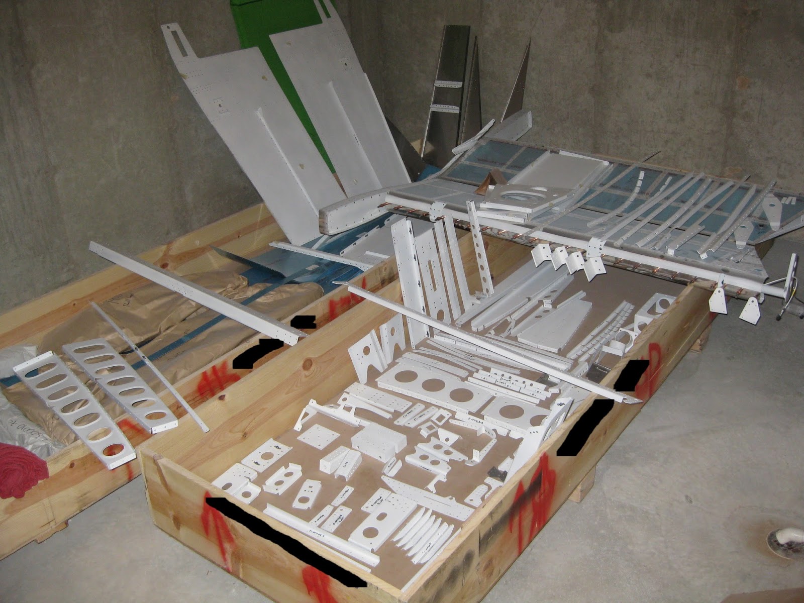
And here are the completed left and right tunnel side assemblies.  The dust is just the result from a routine recent priming session, which is why one wears a mask when priming.


The rivets called for attaching the gussets (outside corner doublers) are AN426AD4-7.  They are too long.  I believe that -6.5 is appropriate.   The -7 rivets too easily clench over whether they are being back riveted or squeezed.  I had to remove about seven rivets for that reason.  I did use my rivet cutter to try setting a -6.5 and it came out just fine.  The -7 rivets have tall shop heads and perhaps could be squeezed/bucked a bit beyond the 1.5 diameter spec.  The image below shows some rivets over the gusset.  You can see how tall the set shop heads are.  In fact, the rivet on the bottom right is not perfect, but not bad enough to remove, in my opinion.  Some spot priming is also visible, following removal of a few clenched rivets.


You'll notice that the right side firewall half has a small area to the left of the F-01401K firewall gusset that has some primer removed.  Well, I chose to squeeze nearly every rivet (the longeron yoke makes that possible), except for those across the F-01401F-L/R angles (the diagonal ones).  I managed to poorly align the squeezer dies (dice?) and squeezed the gusset, causing visible damage, including a small crack just on the edge.  After some time, I worked it out with 220 grit, removing very little material.  I will need to do additional spot priming over that area.  Also, note that the right, middle row rivet isn't ideally set, but it's not worth removing.


To progress further on the firewall requires me to get some tank sealant.  The leftover sealant I had from my fuel tank redo expired 3 months ago.  On that topic, I have learned that some folks use other materials for sealing the firewall (e.g., 3M 2000+ Fire Barrier Silicone Sealant).  There's an interesting thread about that on VAF (IMHO, post #38 is the meat).  I'm sticking with tank sealant.