18 January 2017

Finish: Cowling. Oil door complete.

I needed to add a large spacer to the COWL-00005A Oil Door Hinge so that the COWL-00004 Oil Door would sit at the correct level against the cowl.


I didn't like the gap around the oil door on the cowl.  So my friend went to work to reduce that gap.


First, the gap is filled with flox.


Then it's slowly filed away to get a tighter fit.  The astute will also notice I used flush quarter-turn fasteners for the oil door, similar to my upper cowl.  These little fasteners are from SkyBolt.


16 January 2017

Fun Stuff: Progress pictures.

Normally, my blog posts chronicle the build from a specific part of the plans.  The title of each blog post delineates which kit, section and task, in that order (e.g., "Finish: Cowling. Upper cowl mounting completed.").  However, occasionally I deviate from posting plans-specific information and include such posts in the sparsely populated "Fun Stuff" category.   And that's where this post fits.  It is merely to share some images.  I wanted to post them to mark a great epoch in the build:  The thing looks like an airplane!

This is after the cowling is nearly complete, the engine and prop are mounted, the rear window is installed and the canopy is placed  (I neglected to place the spinner for the photos).  Though each of those items is still not completed, the images are quite indicative of the airframe's final form.


Finish. Canopy and Window. Retrofit complete.

It turns out that in the tail wheel prototype, Van's found that there is some canopy flex at high speed.   So they released a revision to the kits in Jan-16 that directs builders to place locking pins along the C-01427-L/R Aft Canopy Rail Flange and C-01409-L/R Aft Canopy Rail that fit into the F-01421B-L/R Aft Canopy Decks.  Thus, this retrofit required some modifications.  Later kits included both the additional parts and pre-punched rails to accommodate this revision.  However, all builders must modify the Aft Canopy Decks (as each canopy fits slightly differently due to manufacturing tolerances and builder technique).

The process is quite straightforward and not complicated.  It's a well thought-out set of instructions.

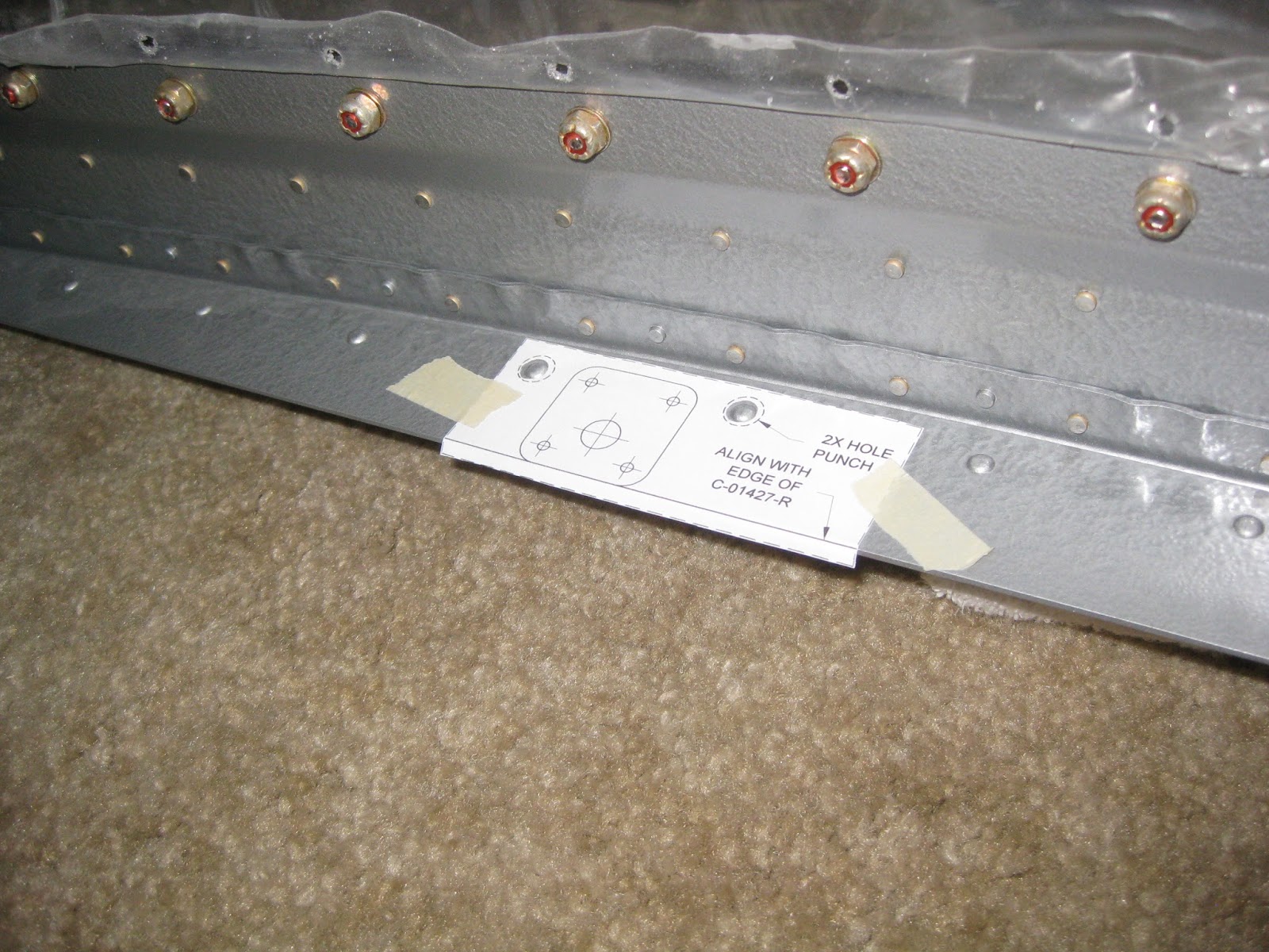
First the template for the C-01453 Guide Pin is properly placed.


Requisite holes are drilled.


The guide pins are riveted (after proper preparation and painting).  I found I that AN470AD3-5 rivets, rather than the -4 that were called out for, were appropriate where there is more material.  The right image shows how the Guide Pins will never hold their paint as there is some contact with the Guide Plates when the canopy opens/closes (see below for description).


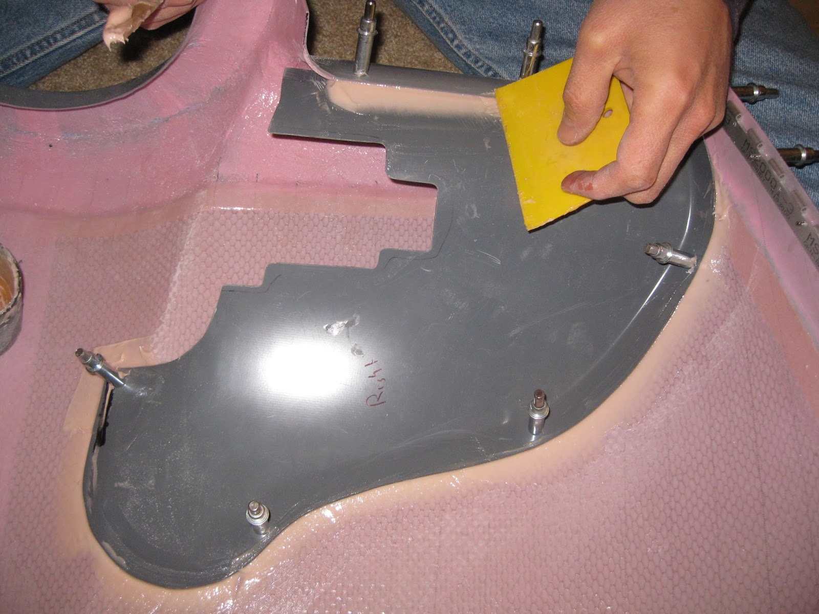
Clay is placed on the Aft Canopy Decks and the canopy is slowly dropped so that the guide pins just contact the decks.


A hole is drilled at a specific location in that clay, the clay is removed and the template with the C-01454 Guide Plate is positioned.


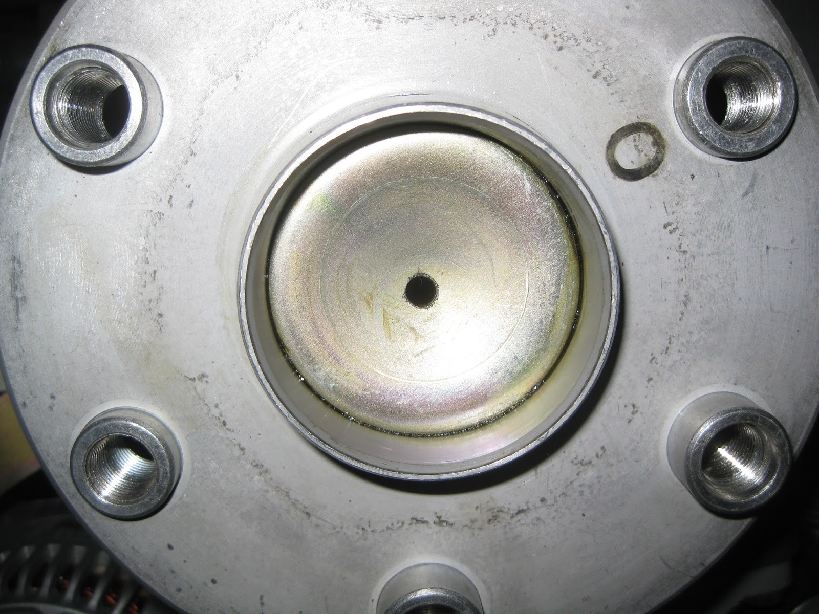
Mounting holes are match drilled and the hole for the Guide Pin is enlarged.  It's worth noting that the forward/aft position of the hole need only placed well enough, and be large enough, so that the Guide Pins can rotate (along a very large arc) into the Guide Plates.  This is why the hole is so much larger than the Guide Pins' circumference.  The inboard/outboard positioning of the holes is much more critical as that position is what locks the canopy into place along that axis, preventing flex.  This is why the Guide Plates are oblong with their axes oriented along the rail.


The Guide Plate is then countersunk (use a 120° countersink bit for CS4-4 rivets!), prepped, painted and riveted.  With the canopy closed, one can push on its sides to test the effectiveness of the retrofit.


The Guide Pins do not contact the Guide Plates when the canopy is opened from the inside using the hand hold at the top of the canopy.  However, when opening the canopy from outside with the little C-01437-L/R Canopy Handles, there is enough flex in the canopy to cause slight contact between the pins and plates.  This is what causes some paint on the pins to be rubbed off.

Finish: Cowling. Inlet ramps installed.

After I trimmed the inlet ramps, my friend completed the installation of them on to the top cowl.  This is not a complicated process, so there isn't much to describe here.

Here he is affixing them with epoxy, mixed with cotton flox.  The astute will notice that I mislabeled left and right on the ramps.


Letting the layup cure.


Completed.

Rudder fairings installed.

I like the look of rudder fairings.  I have no idea if they are appreciably helpful in an aerodynamic or any other sense.

Riveting them in wasn't a realistic option since there is very little space for any rivets to reside due to the foot print of the F-01497 Cable Guides.  So I decided to adhere them with sealant.  The first step was to mark off the contact area that each fairing would encompass.  And draw a line collinear with the axis of the cable.


Then scuff it.


Sealant was applied (not shown) then the fairings were kept in place with ridiculously strong magnets.  The fairings were aligned properly to the axis of the cables.


Following sealant curing, here is the right fairing...


And the left fairing.


Quick and easy.

Finish: Canopy and Window. Rear window installed.

The plans have us seal the rear window in place by placing sealant between the skin and window.  However, some builders have found that the resulting visibility of the sealant through the window, as viewed on the inside of the airplane, is undesirable.  It has been suggested that the window can be painted to hide the sealant.  I thought that was a great idea.

So I temporarily placed the window and masked off the edge.


I mounted the window in my "paint booth" (a.k.a., freaking cold garage floor).


I made sure to cover all areas that should not get painted, scuffed the edge to give the paint something to bite into (left) and painted the edge (right) the same as the interior.


When fitting the window originally, I neglected to dimple the top center hole because at that time the task seemed insurmountable in the confined area.  I decided to use a nutplate and a screw to make the dimple.  Whilst the form of the skin around my "screwed-in dimple" is different than other, legitimate dimples, no one will notice.


Because sealant is used to seal the window, masking tape is very carefully placed to meet the skin edge (left).  Then the sealant is applied (right).  My friend is camped out in the baggage area (a.k.a., "economy seating").


Here is the ELT antenna after the window was installed and prior to lifting the masking tape.


The goopy mess (left) after shoving sealant into the joint.  And the removal of the masking tape (right).


The edges look clean.


The sealant is not visible on the inside.


I wanted to show that at the center of the rear window, where the window attaches to the F-01432A Roll Bar Brace, I had to use an additional thin washer to prevent the window from deforming into the F-01431A-FL/R Roll Bar Frame.

15 January 2017

Antennas: 1090 MHz ADS-B in antenna installed

My SkyRadar DX ADS-B provides ADS-B in on both 1090 MHz and 978 UAT, thus it needs two antennas.  Van's has a provision for a blade antenna on the right side of the airframe, behind the bulkhead (including another for ADS-B out on the tail).  I placed the SkyRadar's 978 MHz UAT antenna at that location, when I originally installed most of the antennas, since that antenna obviously should be downwards facing.

However, for the SkyRadar's 1090 MHz ADS-B in antenna, I spent a lot of time thinking about if I should put that blade on the top or bottom of the airframe.  There are good reasons to do both.  I actually wanted to put it on the top, however I couldn't stomach the aesthetics of a blade antenna sticking out on the top of the fuselage.  So I placed it on the bottom.

I printed out a template then carefully positioned it opposite the 978 MHz UAT in.  They both are about 1.25" from the inboard rivet lines.  This image is looking up at the bottom center of the fuselage.


I then got on my back and drilled the holes.  Aside from the headlamp I'm wearing, I'm not very visible in the image.  In fact, my friend, who's camping out in the baggage compartment (a.k.a., "economy seating"), is far more visible than I.


The antenna is then mounted.  You can see both of the SkyRadar ADS-B antennas in these shots, as well as the two comm antennas forward of the blades.


14 January 2017

FWF: Engine installation. Expansion plug removal.

When I build my airplane, I like to do many of the steps twice.  Well, not really.  It happens because I make a lot of mistakes.  And this one falls into that category.

The Lycoming IO-390 installation manual clearly states, on page 26 (Rev June 2009), "If a constant speed propeller is to be used, the expansion plug must be removed from the crankshaft."  I didn't do that when I originally placed the propeller.  So I had the pleasure of removing and reinstalling the propeller.  That's not a very difficult, nor time-consuming process.  It's merely a frustrating interstitial step that imposed itself due to my neglect.

Following removal of the propeller, the expansion plug is visible on the engine crankshaft.


After drilling a 3/16" hole in the center, the plug is beaten until its shape changes enough to pull it out.


A view down the crankshaft sans expansion plug.