Showing posts with label 35 Upper Forward Fuselage. Show all posts

29 May 2017

Fuselage: Upper forward fuselage. Top skin riveted on.

Back in November 2015, when I mostly completed the upper forward fuselage section, I opted to not rivet on the F-01471 Forward Top Skin so that I had complete access to the area behind the subpanel during my wiring endeavors.  

Now that wiring is complete, it was time to put on the Forward Top Skin.  There are three complicating factors.  1)  The C-01440-L/R Canopy Hinge Bracket bolts make access for riveting difficult.  No joke:  We used chopsticks to keep the bucking bar aligned. 2) The skin needs to be entirely sealed with sealant.  Finally 3) it ain't fun being the guy with the bucking bar.

When cleco'ing the Forward Top Skin in place, I found that I could not get the holes into the longeron to line up properly.  Which is odd, because back in November of 2015, the F-01488-L/R Upper Engine Mount Brackets were match drilled into the skin whence the skin was cleco'd originally from the center to the sides.  However, I found that if I cleco'd the sides of Forward Top Skin first, I could get excellent alignment.


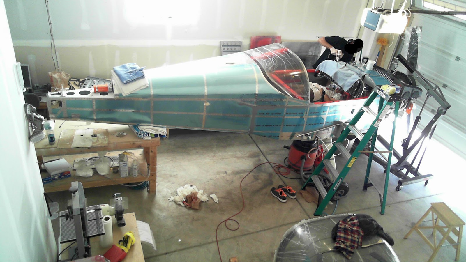
My poor friend drew the straw for holding the bucking bar.


Here we are, riveting away.  Sealant is applied to all flanges prior to cleco'ing the Forward Top Skin on.

 
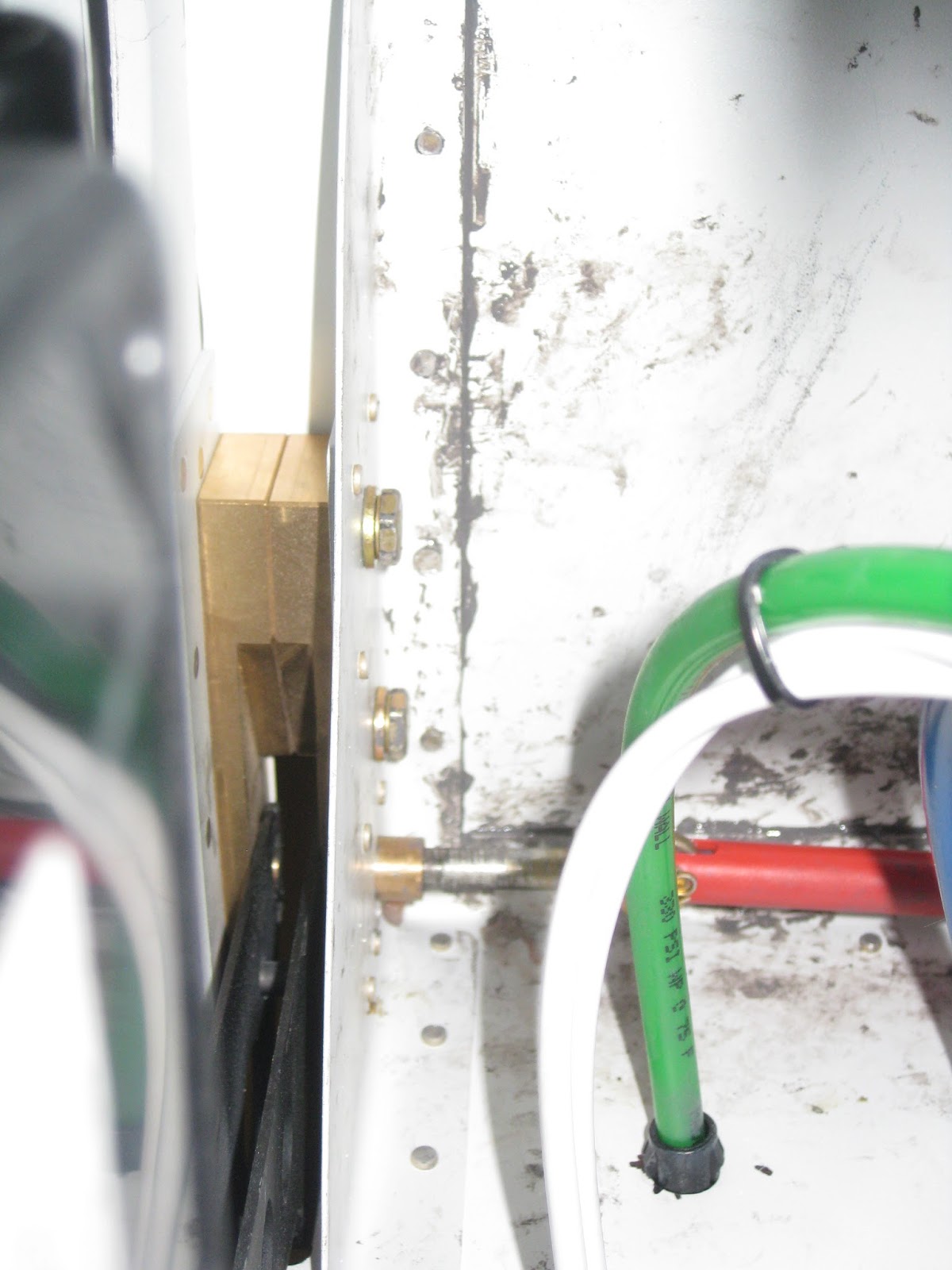
On the Upper Engine Mount Brackets, the bolt holding the FF-01400 Dyna-1 Tri-Gear Engine Mount prevented good access to bucking the forward-upper-most rivet.  I didn't want to risk messing up this important area of the airframe.  So I checked with Van's if a CherryMax CR-3212-4-5 could be used rather than the AN426AD4-7 (which is what is done for the analogous rivet on the F-01489-L/R Lower Engine Mount Bracket).  They approved of the substitution.


Here are the Upper Engine Mount Bracket rivets from the outside, on the right side.


Here are the bucked rivets on the left and right mounts.  They are acceptable.


A few pictures showing the sealant results.  It got messy in there, but no worries:  No one will see it.


Then the flanges for the SkyBolt quarter turn fasteners were riveted in.  These were fitted back in December of 2016.


Next step is finishing up the sealant application.


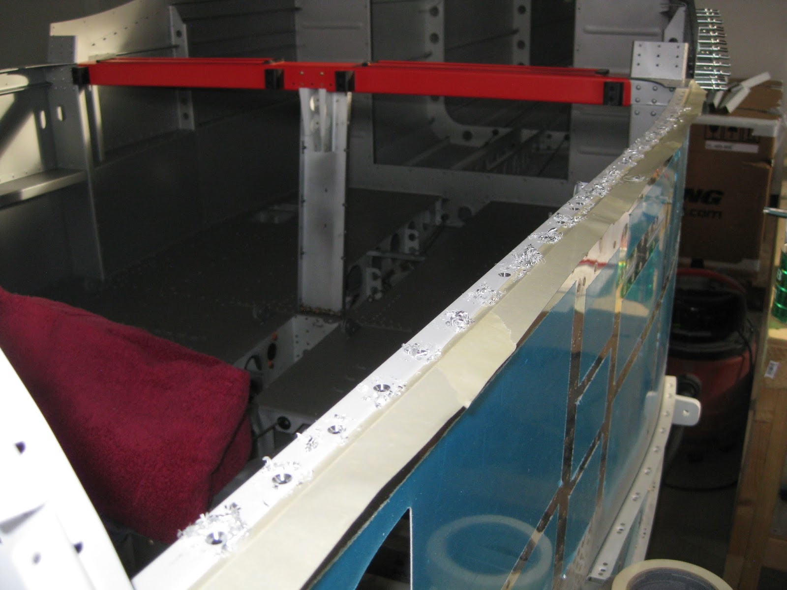
It's important to fill with sealant all of the relief notches on the forward and aft edges.  When this cured, I painted it the interior color


Then I applied another layer of sealant because I didn't like how the first one came out.  I am please with how this finally came out.  What you're seeing below are the lower edges of the Forward Top Skin where it meets the F-01455 Sub Panel.


Here are shots showing the relief notches filled with sealant.  The rivet in the left picture was later replaced (in fact, it was this very picture that showed that the rivet was unacceptable).


All done (my friend is reworking the top cowl left side).

02 November 2015

Fuselage: Upper forward fuselage.

The upper forward fuselage assembly (primed last December, January and February and completed back in March) is cleco'd into place.  It's easily riveted in solo.


The F-141016 Wiring Channel is then riveted in.  The plans call for LP4-3 rivets on the joining of the wiring channel to the F-01451-L/R Tunnel Sides.  I was easily able to set AN470AD4-4 rivets with my longeron yoke.


Then the F-01421A/B-L/R Canopy Decks are match drilled into the longerons.  It's important to clamp everything down.


Eventually, each hole becomes a #30.  The Canopy Decks are removed, deburred and dimpled.  You might consider using a 120° dimple die as you'll be putting CS4-4 rivets (I used 100° on accident though it turned out looking well enough).  The longerons are then countersunk (a few holes are not, be careful).  I supposed if you went with a 120° dimple die, you'd prefer the same angle on your countersinks.


I suggest using a run of tape down the longeron to prevent countersink shavings from impinging into the space between side skin and longeron.  I didn't take such a precaution on the right side and spent some quality time removing shavings out of that space.


I opted to paint my canopy decks red, in keeping with my accenting many parts in red (rudder pedals, seat back guide, wiring channel, shoulder harness lugs and red harnesses).  The decks are really only visible when the canopy is open.  I suspect these parts will get scratched and the paint will eventually look ratty.  I'll keep an extra can of spray paint around or I may have the decks painted with the exterior paint when that time comes.

And yet again to prove that I still lack discipline in building my airplane...I had just returned from a 2 week business trip to Japan and was waking up at 3 A.M.  What better thing to do than work on the build?  So I went to town and put in the canopy decks only to later realize I forgot to lay down sealant along the longeron as called for on 35-11, Step 14.  Ugh!  I had to drill out all 65+ rivets.  Turns out that went much quicker than putting them in.  I then had to drill out and remove the rivets a second time as I realized I didn't use enough sealant.  Never work on the plane when sleep deprived!

Here's how it turned out.  I like the contrast between the unpainted rivets and the painted decks.  My guess is the paint won't hold up. 


Next the panel frame assembly (completed back on 31-Jan-15) is placed (left).  After doing so, I realized I wanted the parts painted since much of this area will be visible when the canopy is opened.  So after spending a good hour masking everything off, it got painted (right).  In retrospect I wish I would have painted the frame and upper forward fuse assemblies prior to installation.


Then it comes time for the canopy release mechanism.  I used a Dremel with a cutting wheel to lop of the ends of the release pins.  Then some excessively liberal use of the grinding wheel yielded this.  Hopefully too much wasn't taken off.  Luckily it's a marginally difficult to replace part if that was the case.


When cutting the C-01435-L/R Canopy Release Pushrods, be careful to include the 1/4" extra on both sides.  I did on the longer one, but not the shorter, causing me to buy to a replacement AT6-058X3/8 tube.


Update 23-Dec-16: I later dispensed with the hinges along the top in favor of quarter turn fasteners.  That process is illustrated here.

Then the F-01471 Forward Top Skin get cleco'd in place for match drilling the FF-00006A/C Cowl Attach Piano Hinges.  As I learned from the FF-00006B-L/R hinges from Section 29, drilling the pilot hole can lead to a poorly aligned hinge.  So I dispensed with that step in favor of clamping the part securely after lining it up properly, then drilling/cleco'ing.


Eventually it all gets match drilled.  Later the hinges need to be countersunk and the skin/shims/firewall dimpled. 


I have elected not to rivet in the forward top skin (a.k.a. "boot cowl") until after wiring of the panel and engine are complete in an effort to support easier access to the firewall and instrument panel assembly.  So work on this section terminates in anticipation of a future continuance. 


03 March 2015

Fuselage: Upper forward fuselage. Upper forward fuselage assembly completed.

This is a fairly straight forward part. As I typically work solo, I have to support my work so I have something to work against when applying forces to rivet.


I would suggest riveting the F-01477-L/R connector brackets to the F-01494-L/R instrument panel standoffs before riveting the standoffs to the upper forward fuse assembly.  Putting the brackets on earlier does not impede access to the rivets attaching the standoffs to the assembly.


I was able to squeeze the aft-most rivets.  But it's extremely difficult to access the forward-most AN426AD3-3.5 rivet on each bracket.  I had to come up with a creative way to do it.  Below you can see how I situated a back rivet plate in just the right location.  With my 12" extended back rivet set, I was able to hit it. 


The upper forward fuselage assembly awaits its turn to be fastened to the upper forward fuselage.


29 December 2014

Fuselage: Upper forward fuselage. Countersinking vs. dimpling panel flange doubler.

Page 35-13, step 2 calls for the F-01467B panel flange doubler (the thin strip at the top) to be countersunk.  I couldn't figure out why that's called for given just how thin that piece is (0.032").  Seems like dimpling the mating parts would be a better way to go as, even though 0.032" is acceptable to countersink (page 5-08), it's too easy (for me, anyway) to elongate the holes, as I experienced with my original fuel tank skins.


I put in a query to Van's to see why countersinking was called for rather than dimpling.  Their response was simply that "The .032 material could be dimpled or CSK.  In this case we chose to CSK it."  Whilst that doesn't answer my question, that ultimately isn't important as it confirms that dimpling would be okay.  So that's what I chose to do for F-01467B and the F-01467A-L/R instrument panel angles.  Because this will be a visible and touchable part of the plane for the occupants, it's important to me that it look and feel nice, with no prideful or sunken rivets due to any less-than-optimal countersinking on my part.

Van's may have wanted this part countersunk because the dimpling would cause the thin, curved piece to distort, just like the W-1019-L/R splice strips on the wings.  Effectively, the stretching of the aluminum around the dimple can aggregate over many dimples to deform an entire piece.  And it turns out the piece did just that following dimpling.  But it's easy enough to bend it back.