31 December 2014

Fuselage: Multiple sections. Priming.

The weather here has been brutally chilly with abundant snow, making the outdoors cleaning and etching process impractical.  So I was resigned to cruise far forward into the plans to prepare parts for later priming.  I had accumulated such a pile of aluminum that I decided to clean and etch the smaller parts in my kitchen sink after verifying the etchant does not discolor my sink and/or counter.

Everything laid out (the visible parts already primed needed a few touch-ups).


Primed.  As usual, I used my HVLP gun and two part epoxy primer.


Wow.  I believe I have quite the collection of primed parts.  This is directly a consequence of my running out of space in this tiny ~1,200 square foot house with a ~600 square foot basement, as I feverishly jump ahead in the plans getting as much as I can ready for later assembly.


My wings are in my living room, empennage on the couch, horizontal stabilizer in the kitchen, scrapped horiz stab and fuel tanks in the detached garage, and vertical stab and rudder are in the guestroom.  And there is still a pile of prepped aluminum in the hallway ready for priming.  If all goes according to plan, I'll have a real garage to continue building in March.  For now, I'm fairly limited in how much further I can go.  Definitely not the fuselage side structure.

29 December 2014

Fuselage: Upper forward fuselage. Countersinking vs. dimpling panel flange doubler.

Page 35-13, step 2 calls for the F-01467B panel flange doubler (the thin strip at the top) to be countersunk.  I couldn't figure out why that's called for given just how thin that piece is (0.032").  Seems like dimpling the mating parts would be a better way to go as, even though 0.032" is acceptable to countersink (page 5-08), it's too easy (for me, anyway) to elongate the holes, as I experienced with my original fuel tank skins.


I put in a query to Van's to see why countersinking was called for rather than dimpling.  Their response was simply that "The .032 material could be dimpled or CSK.  In this case we chose to CSK it."  Whilst that doesn't answer my question, that ultimately isn't important as it confirms that dimpling would be okay.  So that's what I chose to do for F-01467B and the F-01467A-L/R instrument panel angles.  Because this will be a visible and touchable part of the plane for the occupants, it's important to me that it look and feel nice, with no prideful or sunken rivets due to any less-than-optimal countersinking on my part.

Van's may have wanted this part countersunk because the dimpling would cause the thin, curved piece to distort, just like the W-1019-L/R splice strips on the wings.  Effectively, the stretching of the aluminum around the dimple can aggregate over many dimples to deform an entire piece.  And it turns out the piece did just that following dimpling.  But it's easy enough to bend it back.

Fun Stuff: Number of rivets in wing, empennage and fuselage plans.

I counted the rivets called out for in the fuselage plans and updated the chart on the lower right of the blog's main page.  Here is just the fuselage rivet count.

Number of Rivets in an RV-14A 
Fuselage only (see complete chart here)

25. Fwd Mid Fuselage Bulkheads 284
26. Mid Fuselage Lower Structure 1,308
27. Firewall 439
28. Fwd Fuselage Lower Structure 541
29. Fwd-Mid Fuselage Side Structure 1,396
30. Aft Fuselage Attachment 465
31. Fuel System 30
32. Baggage Area 644
33. Rudder & Brake Systems 108
34. Flap Actuation System 0
35. Upper Fwd Fuselage 602
36. Aileron & Elevator Systems 51
37. Roll Over Structure 382


Empennage 4,446
Wings 8,276
Fuselage 6,250
FWF

Total: 18,972
The tail dragger would be very, very close to this number (in fact, same for wings).

I will update this list as my build progresses.  As always, it will live on the blog in the right column at the very bottom underneath the parts origin and skin thickness lists.  Direct link will be http://rv-14a.blogspot.com/#rivet_number

Want to wrap your brain around the mindlessness of the tasks involved in building a kit plane?  Consider that each of those rivets represents at least one hole (sometimes many more when parts are stacked) and each of those holes gets at least two deburring tasks and sometimes match/final drilling and/or countersinking/dimpling and/or sealant application too.  You can then calculate an upper-bound on the number of tasks per hole using some worst-case assumptions:  Just 6x the number of rivets to get a grasp on the number of tasks involved with the holes.

26 December 2014

Fuselage: Baggage area. Seat back hinges.

There are a set of six seat back hinges composed from AN257-P3 hinge.  The plans call for each of the six to be 10.5 inches long.  Much like for the elevator trim tab hinge, a locating hole is started on one end 1/4" from that end.


Following match drilling the 6 hinge pieces to the F-01447-L/R baggage floors, it turns out that the final hole violated the edge distance requirement (not sure if it applies to LP4-3 rivets, but seems it would).  I determined that this occurred because I didn't factor in the kerf of my band saw blade, so the hinge ended up shorter than 10.5".

You'll notice in the picture below that I used the wrong hinge on my first attempt.  The bottom hinge is piano, whilst the top is my replacement AN257-P3 (primed).  I didn't realize this mistake until my replacement AN257-P3 arrived.  I thought Van's sent the wrong one, until I saw it was marked properly.  So, I'll have to order replacement piano hinge now.  It's inexpensive, but because it's 6', shipping is high.  I might wait to consolidate that into the finishing kit.


When I went to match drill the replacement hinge, rather than risk hollowing out the holes in my baggage floors with more match drilling, I matched drilled the AN257-P3 to the piano hinge.

As an aside, here is a nice tutorial on structural vs. non-structural breakstem rivets.  At this point, I'm not certain which family LP rivets are, but it seems to be one of those listed at the bottom of that tutorial page.

25 December 2014

Fuselage: Forward mid fuselage bulkheads. Replaced.


My new bulkheads and associated parts came in a quaint little crate.


This time the bulkheads were packed with some material between them to isolate the parts.  When shipped in the fuselage kit, they do not come that way and end up with some surface marring.  Guess there's one good thing about having to replace these, right?


So, not wanting to repeat the 
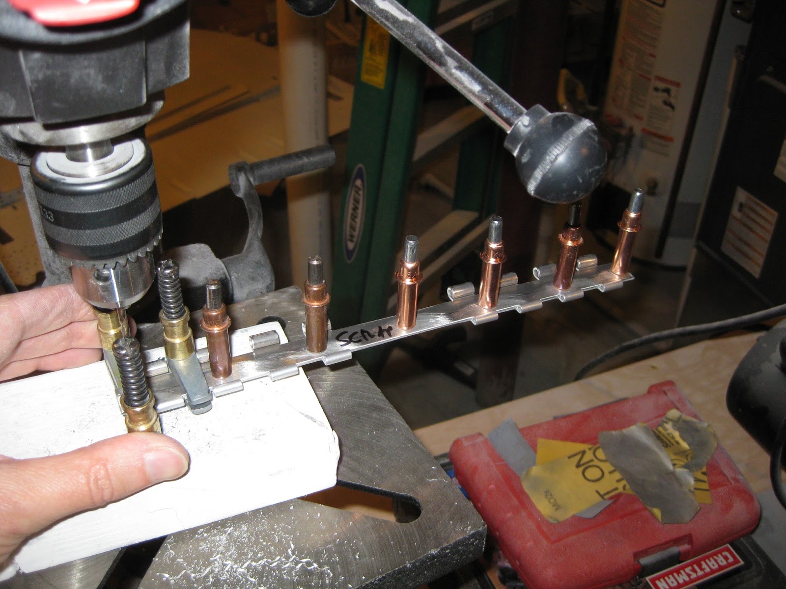
mistake made on reaming the original bulkheads, I opted to do it myself in my shop.  You'll notice that the cover ribs are not yet on the forward bulkhead, but the angles are.  I decided to ream the bulkheads before the cover ribs are riveted on, contrary to plans.  This makes the assembly easier to negotiate on the drill press.  You'll also notice judicious clamping and cleco usage (latter isn't visible) to ensure the bulkhead web sits flush against the flange at all times.


Van's reams the bulkhead parts at the factory (this is verified by communication with Van's).  Thus, if everything is lined up properly, the reamer should slip in and out of the bulkhead hole with no friction.  That is how I ensured alignment.  Once I could lower the reamer down into the hole with no impediments, when on the chuck, I lubricated the reamer, fired up the drill press and very slowly dropped the chuck to ream the angle and webs.  Below shows just how little material needs to be removed. This was after reaming a 0.375" hole in the angle.  The material that was removed appears to be mostly primer (due to the camera's flash), but it is aluminum.


Using gauge pins (both 0.375" and 0.311"), it's easily verifiable that my reamed holes are perfectly cylindrical and quite snug.


With that out of the way, it was time to rivet the associated ribs on to both bulkheads.  I mostly used the same approach as on the original bulkheads.  Except...

Turns out that the longeron yoke can reach a lot of floor rib rivets.  I wish I had realized this before I had bucked almost all of the other rib-to-bulkhead rivets.  In fact, I believe it could be used to rivet the topmost rivet in the cover ribs, which I had to put on backwards because I couldn't find a way to get the rivet set in there.


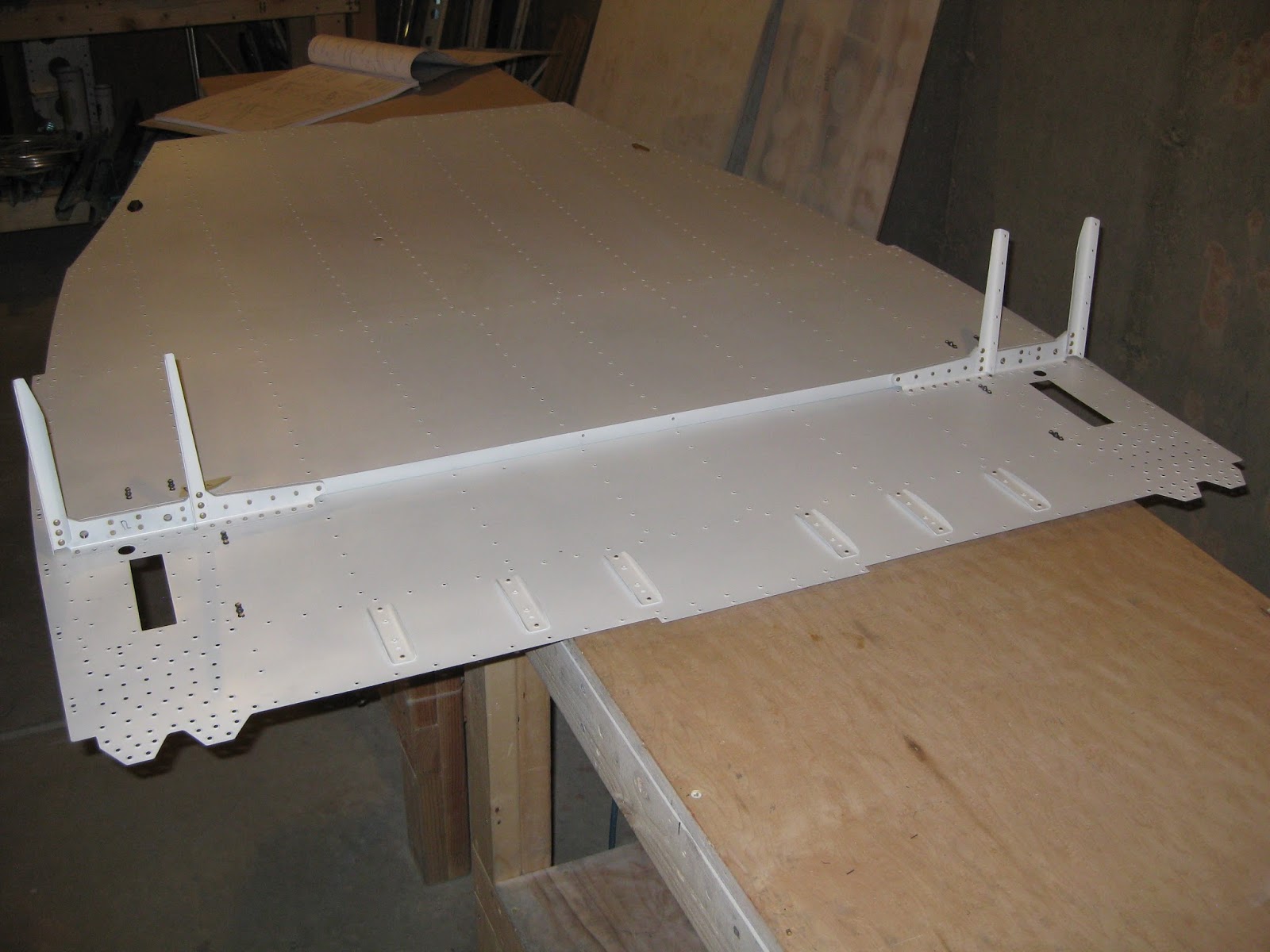
And here the aft bulkhead assembly sits awaiting mating to the skin.


21 December 2014

Fuselage: Forward mid fuselage side structure.

The arm rests each have a hole which must be dimpled, yet is inaccessible with my DRDT-2 or with a yoke-equipped squeezer. 


I found that a male squeezer die, the female side of a pop rivet dimpler set placed on a back rivet plate and a strategically drilled 0.187" hole in a footed bucking bar, managed this hole just fine.  Left is the male die in the bucking bar over with the arm reset inbetween that and the back rivet plate with a female die underneath (the latter isn't visible).  Right is everything ready for a hard whack with a hammer.


And here is the dimple.  Not bad.


The seat back adjustment guides need to have their corners radiused (is that a word?).  Turns out I was spot on using my Scotch Brite wheel.


20 December 2014

Fuselage: Forward mid and lower structures. Priming.

As usual, priming is an unremarkable affair.  Used my HVLP gun and two part epoxy primer.


First the forward lower skins.


Then everything else.


The astute might notice the F-01421A and B aft fuselage bulkhead pieces.  I'm going to try to replace the ones I currently have due to what happened here.

Fuselage: Friend's progress.

Less than two months after receiving his kit, one of my fellow builders sent me these pictures of his fuselage.  He's a speedy builder.  He completed his empennage in less than 30 days.


See his earlier completed empennage and his later completed finish kit.

18 December 2014

Fuselage: Forward fuselage lower structure.

The plans require a break of the bottom skins at an unusual location.

Update 26-Aug-16:   No they don't.  The edges of the skins aft of those lines get a break.  See here on VAF.  Whoops.  When this was ultimately riveted to the mid fuselage lower structure, the edges had a good layup regardless.  These are the kinds of mistakes that make one feel like a fool.


Here's how I approached that, with a little elbow grease.  Don't do this.  See above.


One pair of my VENT-00001A-L/R vent sides did not come with the holes drilled.


Not a problem.  I just drilled them in matching to the other sides.  If you look closely, you'll see I was a millimeter or two off, but everything still lined up well on a test fit with the firewall and vent.


The vent inlet assembly uses some stainless steel rivets, MS20427F3-3.5.  I chose to squeeze these.  It takes noticeably more elbow grease to set these rivets as compared to an aluminum AN426-AD3-3.5.  Below are the assemblies.  I only need to dimple the holes marked "F" on the right (which is the left assembly) to accommodate the error I made in dimpling the left firewall side.  I'll need to pick up a set of dimple dies so I can grind down the male die to fit that confined area I need to dimple.

07 December 2014

Fuselage: Mid fuselage lower structure. More riveting.

The gear brace angle gets riveted to the center bottom skin.  Later, the forward bottom skins overlap the center bottom skin.  So not all rivets are placed yet.  Back when I cut out the gear leg holes in the forward bottom skins, I had traced the overlap onto the center bottom skin.


With all the gear brace rivets taped in, the tracing makes identifying the rivets to be left out an easy task.


A builder posted to VAF showing that it's difficult to access the shop ends of the rivets under the inboard angles on the gear brace.  Van's agreed, suggesting that the angles be riveted onto the brace after the brace is riveted onto the skin.  Luckily that builder was also in touch with me prior to my reaching that step.  I was able to ensure the angle was orthogonal when riveting it in the modified order.


Completed.


05 December 2014

Fuselage: Forward mid fuselage bulkheads. How to ruin them.

The bulkheads have some bolt holes that are used to hold the bulkheads together after they've clasped a "lower drag fitting" (see page 29-03).  These holes should have a tight tolerance.  The holes in the bulkheads were reamed to size at the factory (as verified by consulting with Van's).  However, the holes in the mating angles and bulkhead webs have not been.  The builder is tasked with reaming them him/herself once the parts are mated.


To properly ream, one ought to use a drill press to prevent the introduction of an incorrect bit trajectory.  Negotiating these bulkheads on a consumer drill press is difficult.  So I enlisted the help of a friend with a legitimate shop that has a milling machine and more spacious digs for the task.  Well, turns out things didn't go well at all.  Below are some pictures showing some of the holes with and without the proper bolts.  The issue is obvious.


I believe the problem was caused by the reamer not being properly lined up with the holes to be reamed.  I think the reamer came in at an angle.  Lots of material came off the reamer and the lubrication got hot enough to smoke.

Unfortunately, this is an example of always being sure that you understand every element of the work being done, especially when someone else is doing it for you.  I let my guard down and should have being more proactive in involving myself in this process.

Anyway, the parts needed to be replaced.  For the curious, new bulkheads cost $575 for the forward and $540 for the aft.  Angles cost $11.10 each for the forward and $19.30 for the aft.  Cover ribs are $12.00 each.  So that's a good time.

Click here to see the post involving the redo of these parts.