Showing posts with label 26 Mid Fuselage Lower Structure. Show all posts

17 February 2015

Fuselage: Mid fuse lower structure. Baggage ribs to skin.

The baggage ribs have been riveted to the F-01484 bottom center skin thanks to help from a friend.

The assembly sat ready for the process on a bed of its own clecos.


As with the seat ribs, we kept the assembly vertical as it lent itself well to the riveting process.


It wasn't too burdensome to reach the rivets.  The deltoids indeed accumulated a surplus of lactic acid during the high reaches.


And here is the completed assembly.  Section 26 is officially complete.


18 January 2015

Fuselage: Mid fuse lower structure. Seat ribs to skin.

First the rib and bulkheads frame is set up.


Then the skin is tacked on with clecos (left).  I used two baggage ribs to prevent the skin from flopping over.  Following four hours of help from a gracious friend, the seat ribs are on (right).


Next comes the baggage ribs.  Each one gets riveted to the bulkhead and/or adjoining seat ribs.  These AD4 rivets are difficult to reach.


For that, it was time to bring out my double offset rivet set.  This thing can be evil.  If it isn't restrained, it will rotate and wreak havoc on the manufactured head, endowing you with a rivet looking back at you with its big toothy smile.  So I secured it with some duct tape (does anyone actually use that stuff on ducts?). I managed to buck every rib-to-bulkhead rivet solo with judicious use of limb and rivet gun positioning.


In a few cases, I had to get creative to offer myself access to the rivets.


Now it awaits a bucking partner to rivet the baggage ribs to the skin.


Fuselage: Mid fuselage lower stucture. Idler bracket bearing.

The idler bracket bearing assembly requires the VA-146 bearing to be cut (page 26-09 shown below).


It's not easy making a straight cut on something round.  So I match drilled two holes into a block of wood so I could cleco the bearing to something solid.


I ended up doing an involuntary trial run on this step.  On my first attempt, I managed to cut the bearing too short (left).  The second attempt was successful (right).  Replacement VA-146s are $23.  Yippee.  I'm pretty sure I'm Vans' best customer (see the cost of replacements on the right column of the blog).


Incidentally, I was curious why the part is called an "idler bracket" since it doesn't seem like it helps hold anything that is idling.  Turns out the term is used to describe the pivoting support for a steering linkage.  In this case, that would be the up/down "steering" of the elevators.

07 December 2014

Fuselage: Mid fuselage lower structure. More riveting.

The gear brace angle gets riveted to the center bottom skin.  Later, the forward bottom skins overlap the center bottom skin.  So not all rivets are placed yet.  Back when I cut out the gear leg holes in the forward bottom skins, I had traced the overlap onto the center bottom skin.


With all the gear brace rivets taped in, the tracing makes identifying the rivets to be left out an easy task.


A builder posted to VAF showing that it's difficult to access the shop ends of the rivets under the inboard angles on the gear brace.  Van's agreed, suggesting that the angles be riveted onto the brace after the brace is riveted onto the skin.  Luckily that builder was also in touch with me prior to my reaching that step.  I was able to ensure the angle was orthogonal when riveting it in the modified order.


Completed.


30 November 2014

Fuselage: Mid fuselage lower structure riveting.

Work on riveting the non-skin related items on the mid fuse lower structure progresses.

There are a couple of ribs, F-01417-L/R, that get F-14100 routing angles (for future wiring, per a recent builder's query to Van's).  It's easy to squeeze the upper and lower rivets, but the middle rivet is just a bit too long for even my 4" deep yoke.  I don't have a rivet set for AN470AD3 rivets, but I do have a squeezer die and a strategically drilled 0.187" hole in a footed bucking bar.  Couple of wacks with the back rivet set and all's well.  Note that so far only 8 of the 10 routing angles are used.  I see no other place in the remaining fuselage plans where the last 2 are used.


The F-00016-L/R step attach weldments represent an improvement over previous models:  The steps are not riveted to the frame but rather are bolted on and removable.  The weldments get riveted to the baggage ribs first.  These rivets are a bit difficult to get to.  The plans call for Cherry blind rivets in the recessed spots and gives the options of Cherrys (ies?) in all spots.


Turns out that they were all accessible with my two tungsten bucking bars (a.k.a., Mr. T) except for the lower, forward-most one.  I have a very small footed bucking bar that could reach it, but it lacked mass and it was clear that the AD4 rivet was reaching incipient work-hardening, so I removed it and went with the Cherry.  This tungsten bucking bar would have made simple work of that one rivet, but for $230, I'll stick with the Cherry.

Using the angled Mr. T to hit the upper inset rivet (left).  And the rectangular Mr. T for the others (right).  The gray primer represents spot priming of the countersunk nutplate holes and final drilled 1/4" bolt holes.


The one Cherry is evident (spot priming is visible and was necessary after removing attempted AD4).


Left weldment's shop heads (left).  Right weldment's shop head (right).  Some spot priming will be necessary where the bucking bars ate the powder coating off the weldments.


The side frame assemblies get riveted to the side frame brackets with the step attach weldments and doublers.  The plans call for using LP4-3 pull rivets in 3 places.


However, I was able to squeeze all 5 rivets on both assemblies using my 4" deep yoke without issue.  Taping the edges of the yoke helps prevent scratching the parts.


The step attach assemblies then get mated to the baggage ribs at the weldments and doublers.


These are tough rivets to set.  In fact, these are the ones that seem most reasonable as Cherry, yet aren't suggested as such in the plans. I opted for squeezing them with my 4" deep yoke.  Five of the six turned out well enough.  One of them was clenched over (not shown).  Ordinarily, I would have replaced it, but given the poor access, I figured I'd mess up the hole and decided to leave it.


Next, the step attach assemblies get riveted to the F-01425-L/R baggage ribs.  Again, tight access.  The plans call for 2 of the rivets on each weldment to be Cherry.  However, I was able to squeeze all of them as AD4s using my longeron yoke.


Completed step attach assemblies (sans nutplates on weldments).


Completed crotch strap assembly.


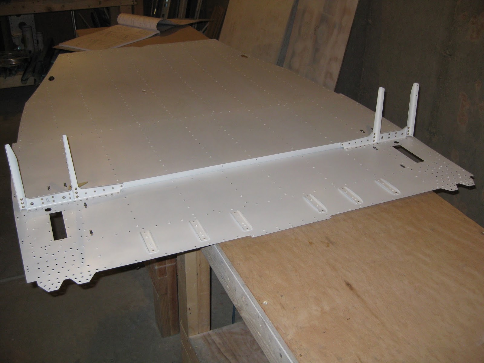
I'm building a tri-gear so my gear will attach to the forward bulkhead (rather than the firewall as for the tail-dragger).  Thus, the plans require cutting the rectangular holes in the 0.040" forward bottom skins to match those of the 0.025" center bottom skin.  I used a combination of my Dremel with a reinforced cut-off wheel, nibbler, files and sand paper to create those two holes.  The holes aren't perfect, but no one will see them and they'll function just fine as-is.  They were rounded and smoothed down to mitigate cracking.  The Dremel got away from me on the right skin necessitating a notching and subsequent smoothing to reduce skin stress.


23 November 2014

Fuselage: Mid fuselage lower structure. Dimpling center bottom skin.

After seeing this thread in VAF, I thought I'd share my approach in the hopes that it's useful.  

The F-01484 center bottom skin is quite large, as it represents one of the defining features of the RV-14:  Cabin width.  So dimpling the holes in the middle of this skin can be a challenge when the throat depth of the DRDT-2 is 22 5/16".  The hardest hole to reach is the one shown below.   The shortest distance to that middle hole is close to 22 9/16".  That's 1/4" too big for the DRDT-2.  Or is it?


Below is my skin following the dimpling of all holes except the center one.  NoteBreak the aft edge of the skin upwards, as called out on page 26-14, Figure 1 (see above), before dimpling is called for on page 26-11, step 6.  I didn't.  I wish I did.


To get to that middle hole, the distance from the edge of the skin to the hole must be somehow reduced by 1/4".  I found I was able to do this by aligning the "notch" in the skin with the DRDT-2's upper arm stand.  With the skin at this angle, this distance is reduced as much as it can be prior to bending the skin.  Here's a verbose description...

Keeping in mind that the distance from the base of the lower dimple die to the bottom of the DRDT-2 upper arm is exactly 3 1/4", then any deflection of the skin upwards in the throat using that space will bring that center hole further into the throat.  So, I pushed the edge of the skin into that upper corner.  It's almost enough to align the hole over the die, but not quite.  Finally, being careful not to permanently distort the skin, I pushed the skin firmly into the DRDT-2 (yes, the skin makes a sort of "pop" sound when you do this) and negotiated the male dimple die into the hole.  Confirming that the skin was flat around the die, the dimple was then applied.  

Following priming, here is the skin with the male dimple die in that hole.  You'll note that the skin is not being held by myself or any other additional artificial means besides the platforms, so with care, this can be done by one person (unfortunately, that's usually me).


A close-up of the approach.  Note the location of the skin's notch in the upper right of the image.  It aligns with the upper arm stand and is pushed upwards toward the upper arm.  Thus, the skin is not laying flat (except around the dimple die, which is important).


Finally, I looked at the Cleaveland and Avery C-frames, and they both claim a 22" throat depth.  So does the DRDT-2, but as I stated above, I found it's actually 22 5/16".  My guess is the technique described above would work for the other C-frames, but I can't be certain.

22 November 2014

Fuselage: Mid Fuselage Lower Structure. Priming.

The mid fuselage lower structure parts have been primed.

First the center bottom skin.


Then the rest of the myriad of parts.


The seat ribs and a few other small parts from this section were actually primed in the previous bolus.

Now I have quite the collection of, drilled, deburred, dimpled and countersunk parts all ready for riveting.