Showing posts with label 18 Fuel Tanks. Show all posts

02 July 2014

Wings: Fuel tanks redo. Old tanks dropped. Replacements mounted.

Because I'm redoing my fuel tanks, I'm really only posting progress reports rather than additional details.  See here for why I'm redoing my tanks.  Technique details on the original fuel tanks are found in their associated posts.
It took 5 hours to remove the original tanks and mount the new ones.  I shudder at the thought of doing this with the wings bolted onto the fuselage (Update 4-Sep-17:  I ultimately had to do that...and shudder I did).  We (my -9A friend and I) took off the aileron pushrods to make things easier.  All bolts were replaced.  The exterior screws will be replaced after the wings are painted.

Here's the left wing without its tank.  Contrast the below with a similar image when the bottom skins were off.  Then contemplate how easy mounting the tanks were back then!


So now the old tanks live in the garage next to their scrapped horizontal stabilizer brother.  I am entertaining suggestions on what to do with these non-flightworthy parts.  Ideas?


04 November 2013

Wings: Fuel tanks. Right wing fuel tank mounted.

I decided to redo my fuel tanks.  See here for why.  The entries specific to the redone tanks are here.

Right fuel tank has been mounted with the help of a generous friend. 


Prior to the mounting, the inboard leading edge rib rivets still had to be bucked.  I had been delaying this since I had a hard time with the left side and subsequently investigated different means for the right side.  I even tried a CherryMax but ultimately removed it since I wasn't comfortable with that approach.  However, this time I had no trouble using the same technique and double offset rivet set as I failed with on the left side.  No idea what the issue was the first time but I'm glad it's behind me.

31 October 2013

Wings: Fuel tanks. Left wing fuel tank mounted.

I decided to redo my fuel tanks.  See here for why.  The entries specific to the redone tanks are here.

Mounted the left wing's fuel tank myself.  Not too bad on my own.  A friend helped me move the right wing off the cradle so I could hit the top screws.  All of the bolts are torqued down and marked with Torque Seal.  The screws are merely "snug" for now.


It's a much larger wing than the RV-9, the only other model I'm familiar with at this point.

21 October 2013

Wings: Fuel tanks. Left tank leak free.

I decided to redo my fuel tanks.  See here for why.  The entries specific to the redone tanks are here.

Just a report that the left tank is leak free and complete.


08 October 2013

Wings: Fuel tanks. The fallacy of "the rivet will fill the hole".

I decided to redo my fuel tanks.  See here for why.  The entries specific to the redone tanks are here.

I've read that an elongated hole (one that exceeds the rivet shank diameter) will be filled by the rivet when swelled by the bucking process.  It made sense to me but I never considered testing the notion and perhaps I misunderstood its extent.  Seems it only holds when the hole is nice and round.  Makes sense now...

I had a AN470AD4-5 rivet on my left tank at the inboard attach zee that I had to remove since it was mis-bucked.  I did a horrible job removing the rivet and really messed up its hole.  I decided to replace it with the same size rivet figuring the rivet would swell into hole.  But since the hole had a bad trajectory (due to the angle of the drill bit), the shop head took on a weird shape and was pushed over. 

Here's what the AN470AD4-5 looked like before being fully bucked.  You can see it is taking on the new and misaligned trajectory of the messed-up hole.


Here's what it looked like after being fully bucked.  Who wants to fly with that?


So I decided to yank the rivet and drill out the hole to accept a AN470AD5-5 (my first such rivet in the build).  Here is what the AD4-5 rivet looked like with its factory head removed but the shank and shop head still in the hole.  Clearly, the rivet didn't swell into the hole even after full bucking.  You can also see where the rivet set came in on the attach zee itself (nowhere near a rivet, embarrassingly!) due to a gross misalignment on my part.  That will be sanded out.


And a super close-up of the hole and the removed rivet shop end and shank.  You can see the two distinct overlapping holes:  1) original and 2) new one from the drill bit during previous rivet removal.  And, notice the shape of the shop head and shank.  Removal of this rivet and upsizing the hole is a necessity.  Finally, you can see how I sanded out the damage to the zee from the rivet set.  That took a good 30 minutes of thumb work with 220 grit.


Here are both sides the AD5-5 bucked into place.  Unfortunately, I hit a smile into the attach zee so I had to spend forever sanding that out (you'd figure with all these smiles that riveting makes me happy).  Very difficult with the factory head so close (I also have to sand out the bucking bar scuff on the inboard rib).  I used 85 psi on the gun and a 2 pound bucking bar to squash this guy down.  He wasn't going down without a fight and I wasn't even up against work-hardening!  Sure hope my low fuel level optical sensors survived all of the violence.

<


07 October 2013

Wings: Fuel tanks. Right tank final testing.

I decided to redo my fuel tanks.  See here for why.  The entries specific to the redone tanks are here.

Time for pressure testing the right tank.  Tip:  Use pretty smelling soap as your bubble-maker.  I prefer the lavender scent to sealant.  A simple small paintbrush helps apply the soap.

After trying to use the clamps the kit comes with, I decided to get something smaller.  The kit's clamps were too big and awkward to tighten.


Pump it up until the balloon inflates.  It took a good 20 pumps for this to happen, even after pre-stretching the ballon.  On one instance, I felt like I was pumping a lot of air in and yet the balloon would not inflate.  So I pulled the balloon body with my hands and pfffft, it inflated!


Leak around the balloon seam.  No biggie.  I removed this balloon and used another one without the wire tie.


Leak around at the cap as indicated by the tape seal (I was able to isolate the filler flange and its rivets).  No biggie?  The plans suggest it isn't a problem.  If it is perhaps I'll need to get a new o-ring for the locking cap.


Leak around this fitting.  Thankfully, it's not the flange.  This fitting just needs to be removed, have some Loctite put on it, then reinstalled.  I didn't apply any thread sealant on it originally.  Whoops.


For orientation, that's the upper fitting the plans have us drill the hole for.  I was curious what it was for.  Perhaps another finger strainer for inverted flight (that sounds fun...um, no it doesn't)?  I asked the guys at Van's and Sterling said it was for a future fuel return line if needed.  Does this mean they thought of everything?  Seems like it so far.


So, all-in-all, the right tank had effectively no leaks (once I thread-seal that upper fitting).  In retrospect, that isn't surprising.  I took a very liberal approach to sealant.  If I were to do the tanks over again, I would not use the deeper dimple dies (dice?) and I would dimple the baffle flanges and the associated skin holes rather than countersink.  Threads abound on that latter subject, but here's one.

17 September 2013

Wings: Fuel tanks. Left tank capacitance probes and baffle install.

I decided to redo my fuel tanks.  See here for why.  The entries specific to the redone tanks are here.

Capacitive probes on left tank are installed.  I had to replace a screw from last week since it got stripped going into the nutplate.  Thankfully the nutplate wasn't damaged.  The work for the left tank was identical to the right tank, so I won't go into as much detail here.

I put the masking tape just over the skin's baffle rivet holes this time.  Turns out it wasn't as useful as I had anticipated:  When the tape is removed, it just takes the sealant bead with it since the bead just fell aft onto the tape.  Here is the sealant on the skin ready for baffle install.  You can see the capacitive probe wire in the image.


As with the right tank I put a very thin layer of sealant on the baffle flanges (shown below) and aft rib flanges.


Here is an image looking aft through the filler flange to see the sealant along the baffle-skin joint.


And here are the "shop heads" of the AD-42H blind rivets along the rib flanges as seen through the filler flange.


I had to remove a AN470AD4-4 rivet I put on the outboard attach zee (it needs a -5).  With all the wet sealant, I realized a "chip catcher" was necessary.


And here is the left tank, inverted for curing.


I also countersunk for and placed the final baffle rivets on the right tank.  After it cures, it will be test time.  Once the left cures I will go through the same process.

11 September 2013

Wings: Fuel tanks. Right tank capacitance probes and baffle install.

I decided to redo my fuel tanks.  See here for why.  The entries specific to the redone tanks are here.

For the installation of the capacitance probes, the RV-9 plans require you to cut a notch out of the vent line bushings to fit the wires.  Well, I had already installed the vent line, so that wasn't a viable option.  I didn't like the Van's method anyway since the wire could still fray up against the ribs with the notch removed.  Turns out there is a 7/16" hole at the top-aft of each rib which must serve the purpose of helping the fuel move around a bit or perhaps a tooling hole.  Since it's at the top of the tank, it wouldn't be a big deal to occlude it a skosh (effectively reducing its diameter) if I slipped in a bushing to carry the probe wires through.  So that's what I did, winding the wires around the vent line to help anchor them.


Capacitive probe on rib 6, inboard and outboard sides, prior to final sealing and tacking of wires.


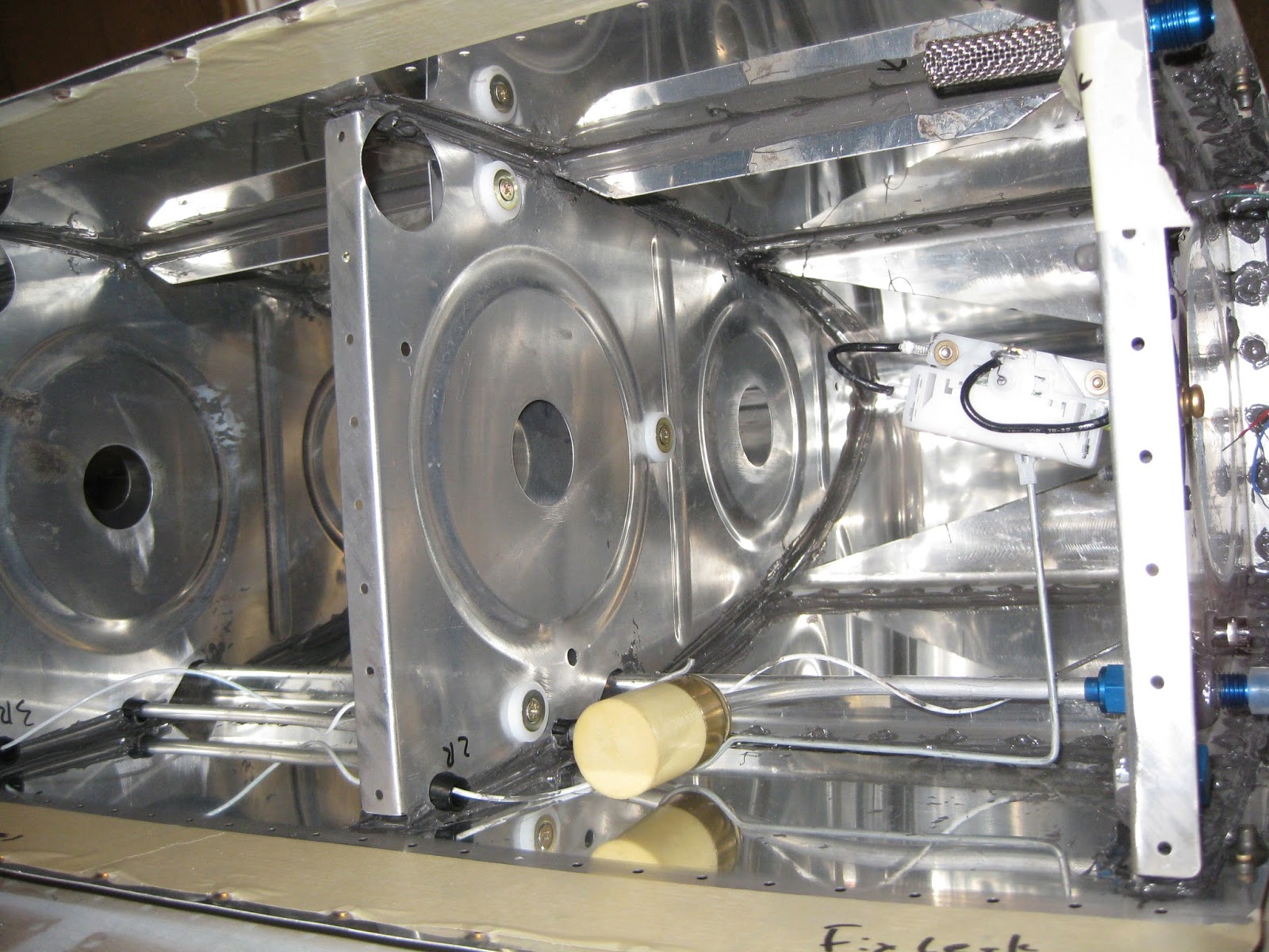
Capacitive probe on rib 2, inboard and outboard sides, prior to final sealing and tacking of wires.  Note the fuel float.  I will be using both means of fuel measuring (one for EFIS, one for steam).  Also the low fuel level optical sensor is visible.

For installing the baffle, since it needs to be sealed on the inside, the plans call for the following sealant methodology.


After dropping in the baffle, using a more liberal interpretation of the above, here's what the sealant looked like prior to the baffle install.  This was done with two stripes of sealant using the manual syringe gun.  For the left tank, I'll integrate some of Mouser's approach to mine.


And here's what the sealant looked like against the baffle inside the tank (the below image was taken through the fuel filler hole).  The sealant bead at the top is the baffle-skin joint (i.e., ignore the arrows).  I also put a very thin layer of sealant (thin enough to prevent skin pillowing) on the inside of the baffle flanges.


And here are the baffle and attach zees cleco'd.  I decided to sand down the primer I originally put on the tank attach zees' flanges so the sealant could get a better grasp of the parts.  May not matter, but surely won't hurt, especially considering how ridiculously tenacious that EkoPoxy/EkoPrime is!


Where the baffle webbing attaches to the ribs, all of the rivets are AH-41/2H blind, except the out- and inboard ones which are bucked AN470AD4.  The latter are very easy to buck solo, just be careful not to let the rivets work-harden prior to getting a good shop head.  Also, there is one AN470AD4-5 rivet on that outboard side that requires a deliberate approach since there is a AN470AD6-5 filling a tooling hole impeding good bucking bar access.

The tank will sit inverted for a week or so to promote better sealing against the baffle.  Probably won't make a difference, but it surely won't hurt.  Every rib and baffle rivet head (shop and factory) and all mating surfaces were slathered with sealant, including a fillet at all joints.


After a full cure, the last baffle rivets will be installed following skin countersinking.  Then it will be 1) final leak testing of left and right tanks, 2) priming of the baffle and outside rib faces then 3) hanging of the left and right tanks.

09 September 2013

Wings: Fuel tanks. Some fuel tank sealing and initial leak testing.
I decided to redo my fuel tanks.  See here for why.  The entries specific to the redone tanks are here.

Prior to the initial leak test, I went through the tanks with more sealant.  This encompassed slathering sealant under the curved surfaces of the J-stiffener and tank attach assembly brackets.  Because these areas are hidden from view, I used the "mirror-on-a-stick" approach to verify the slather. 
Update 17-May-14:  A much better way to approach this is described here.


The various fittings and the low fuel level optical sensors were installed and sealed.


The tanks were then dressed with toilet paper to preserve the evidence of any leaks (odd flashback of my youth notwithstanding).  With the tanks water-filled and a full tube of food coloring dye on board (not sure of the origin of this idea, but Mouser turned me on to it), they each sat for while soaking up life.

The right tank has three leaks:
  1. At the junction of the skin, tank attach assembly and inboard forward nose rib on the forward side.
  2. Filler cap left side at the cap's o-ring.
  3. Filler cap right side also at the cap's o-ring.
A liberal amount of sealant can fix the first one.  The last two will require some investigation.  They might actually be at the filler flange.  I would consider it a free vent, but I don't water to creep into the tank.  Incidentally, I tried with both the locking caps and the stock caps.  Both leaked (bot albeit, slightly different parts of the o-ring).


Right tank filled with water.  Leakage puddle visible on inboard side.  But no other rivet or seam leaks.


Internal bleeding?  No, just food coloring to stain the professional toilet paper detector.  Luckily the neighbors weren't curious about all the red water and associated stains on my clothes.


Left image:  Source of inboard leak.  Right image:  Two o-ring leaks on the cap.


The left tank has no apparent leaks.


No, not a fuel tank hematoma.  Just food coloring.

After fixing the leaks identified on the right and letting the tanks dry, it'll be time to install the capacitance probes and baffles, wait for curing and do the final leak test.

17 August 2013

Wings: Fuel tanks. Fuel vent lines cut and installed.

I decided to redo my fuel tanks.  See here for why.  The entries specific to the redone tanks are here.

Bought a pipe cutter for the vent lines.  The latter are now installed in both tanks.


Wings: Fuel tanks. Right tank ribs and stiffeners sealed.

I decided to redo my fuel tanks.  See here for why.  The entries specific to the redone tanks are here.

The right tank ribs and stiffeners are in, along with the capacitive probe connector.

I bought an extended double offset rivet set to hit the top-most AN470AD4-5 rivet joining the aft and fore inboard ribs to the tank attach assembly.  Turns out this thing is really difficult to use and just ends up work hardening the rivet.  So, in the end, that rivet isn't very pretty.


The plans would do well to have you not rivet the VA-146 Flange Bearing to the tank attach assembly until after you drive that rivet described above.

Both tanks are waiting to have their fuel level optical sensor installed, final sealing forward of the J-stiffeners and fuel float senders (yes, I'm using those with the capacitive sensors).  Then I can leak test prior to putting on the baffles.

What a mess.  I should clean that.