(Performance information is at the bottom of the post.)
The following is perhaps my largest post to-date.
To my knowledge, I am the first person to order the parts for, and complete the conversion from, the 210 HP IO-390-A3B6 to the 215 HP IO-390-C3B6 engine on an already-flying aircraft.
Lycoming provides the powerplant parts required in part number 05K29558Y, which includes the new oil sump, the new throttle body, flow divider, injectors and the associated parts required (though it does not include the new, shorter oil dipstick and flanges for the intakes tubes - more on those points below). It also doesn't include the new billet oil pump or accommodate the removal of the vacuum pad. The "kit" must be purchased through Van's. At the time I purchased that part, it was $7,400. Of course, a number of additional airframe parts are required to complete the conversion, including the new exhaust, snorkel, lower cowl and ramp vent parts among others (I previously already completed the 5" SCAT upgrade). Prior to shipping, the total worked out to be nearly $11,400.
Because this might be considered a "major modification" under FAR Part 43, I contacted my local FSDO in March of 2022 to verify my original flight test area and Phase I duration will remain the same and to discuss the required steps to ensure my registration remains valid. Originally, they thought this would classify as a major modification. However, on 6-Sep-22, they informed me that since it has "no appreciable effect on the weight, balance, structural strength, reliability, operational characteristics, or other characteristics affecting the airworthiness of the product", it's considered a "minor change", so I don't have to reenter Phase I operations.
The order for the parts was submitted to Van's on 2-Sep-21. The Lycoming parts arrived on 14-Mar-22.

The lower cowl and majority of the other parts (sans exhaust) from Van's arrived on 7-Apr-22.
The exhaust arrived on 18-Jun-22. I neglected to take a picture of those parts.
I began the conversion on 11-Jun-22. The initial process involved removing the exhaust and fuel injection servo.
Then the intake tubes and original oil sump were removed.
At this point the engine is looking pretty skimpy and the tail drops markedly since a lot of weight has been removed from the nose of the airframe.
The firewall gets a new passthrough to accommodate moving the mixture and throttle cables to the right side. This is necessary since the new throttle body supports these connections on the right side.
I used my angle drill to make the screw holes for the passthrough and a starter hole for the passthrough hole itself. For the passthrough hole, I used a
knockout punch (coincidentally made by a company owned by Textron) rather than a step-drill since I don't like the results of using the latter to enlarge a hole in stainless. However, the firewall is 26-gauge stainless and is too thin to use that punch, especially without someone on the other side. So this travesty happened.
After cleaning this up by grinding, filing and sanding, I made two doublers out of the same material, one for the front and one for back of the firewall. I sized them appropriately. The passthrough hole was made using a hole saw with tons of Boelube.
It looked reasonable when I test fit on the firewall from the front (left). I match drilled several rivet holes into both plates through the firewall (right). You'll also notice that the firesleeve on that upper passthrough has been removed as have the mixture and throttle cables. That firesleeve was never meant to be removed when it was originally installed, so it was a bit difficult to take out. It required judicious and careful use of a razor blade and pliers.
After applying sealant to the inside of the parts, the rivets were set by back-riveting from the aft side of the firewall. The throttle and mixture cables were finally placed and additional sealant was placed along the seam of the front piece of stainless. It doesn't look too bad, but boy is it a shame that I had to go through that. You'll notice that in this picture, the upper passthough has some new internal firesleeve in, though not sealed nor with the exterior layer of sleeve yet as it's waiting for the ramp flap control cable to be installed.
Next it was time for the new oil sump. On the left you can see the inside of the new sump. It's not as deep as the old sump since it only holds 7 quarts of oil. As a result, the original model dipstick (LW-14760) is too long for this oil sump and even if it did fit, its graduations would be incorrect. The proper oil dipstick (56C23681) is not included from Lycoming. This needed to be acquired separately.
On the right image, you can see the new oil sump in place. To place the new sump, a few mounting studs needed to be removed from the engine case since the new sump uses only bolts. One will also notice that the oil screen is in a much, much better position for servicing. With the previous sump, I had to remove the SCAT tubing to access it. With this new sump, it's trivial to access and inspect. Note: In the right image, I had the blue oil drain in the wrong location. It was later moved adjacent to the oil screen.


The cold air intake and throttle body went on next. The throttle body is much bigger than the previous one. As a result, in order to fit, it has to be tilted when mounted. A plate accommodates that need (left). And the four studs on the intake need to be removed too. As before, that's easy enough by over-tightening two nuts (right) and using the nearer one to back out the stud.
Here's the new throttle body in place. The angled mounting is evident. Again, the blue oil drain was later moved from the incorrect location visible in this image.
Underneath, you can see the WD-00110 IO-390C Cables Bracket installed. Again, the blue oil drain was later moved from the incorrect location visible in this image. Also, this is not how the control cables were ultimately installed. This was when I tried using the placement of these cables through their original firewall passthrough and not the newly punched passthrough. I can confirm that it is necessary to use the new passthrough hole for the cables.
Issue 2: The #2 cylinder's oil return line impedes fitment of the snorkel on my airframe. The left image shows the impediment and the right image shows how the snorkel fits when the oil line is disconnected from the cylinder. Looking at images from Van's demonstrator with the EXP119 (N214VA), they managed to fit the snorkel with the original oil drain line, a feat I was unable to replicate.
Aircraft Specialty makes a drain tube that accommodates the snorkel for $70.
The aft end of the snorkel is then cut and sanded flat to connect to the throttle body. Then a couple of slots are cut (not shown) to accommodate a good seal with the hose clamp.
Now it was time for the new flow divider and injectors. The only complication here is that the fuel lines from the dividers to the injectors, though provided from Lycoming in more-or-less the correct lengths, are not formed. They come straight.
First the original divider and fuel lines are removed (left). Then the new divider is placed (note, I used an AN3-27A on the aft bolt rather than the one provided, which wasn't the right length) along with the new injectors. It's important to note that the injectors are supposed to be torqued and clocked in a specific way. The Lycoming engine manual describes this process.
Next you bend the lines. I basically used the original lines as a template on the side of the injectors. I did try to use a tube bender but ultimately, hand bending them was easier.
Next came time for the ramp flap. The original exhaust used steel hangers in the tunnel. Those hangers protrude below the airframe (left) so I had to cut them off with a die grinder (right).
A few rivets are drilled out from the bottom and nutplates are installed to accommodate the ramp flap and F-14190A Closeout Assembly.
The ramp flap is then ready for installation after its control cable is installed inside the aircraft.
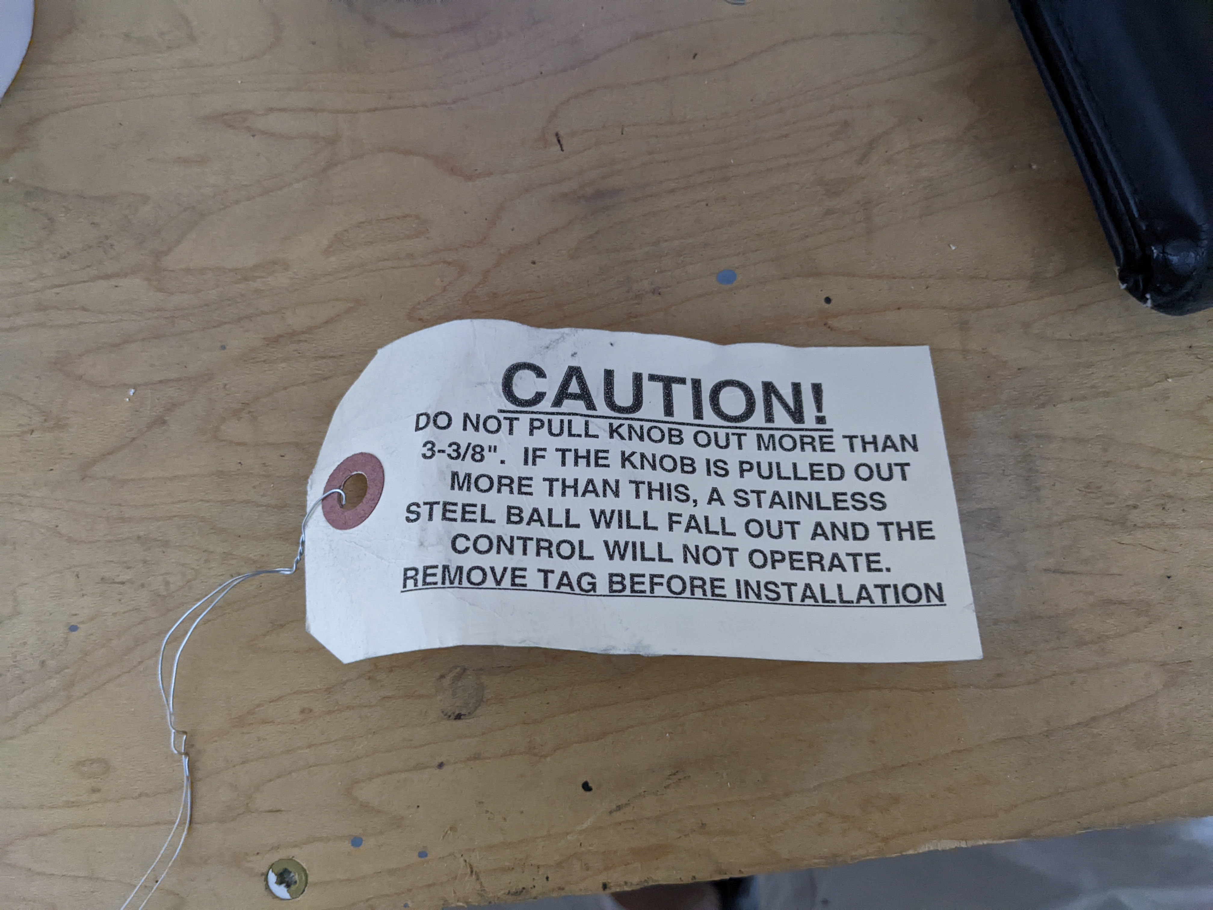
I want to make clear however, that this process is not easy. First, the plans state to pull the control cable out 6 inches, then cut the cable (left). Do not do this! The cable comes with a label that states that if you pull out the control cable more than 3 and 3/8" you will break the cable (right). I can confirm that this will occur. I had to buy another cable for $110.
On the replacement cable, I measured how much of the internal cable would be exposed if I had pulled it out 6", then used my Dremel to very, very carefully cut the outer steel jacket when the control knob was pushed all the way in.
Once the cable is placed inside the aircraft and routed properly, it's not easy to connect it to the Exit Door Assembly. Having tiny hands helps (which turns out, I don't have) and if the cable is too long, it's nearly impossible to coax into the drilled bolt. So I cut it quite a bit shorter so it was easier to handle.
Here's a short video of the ramp flap in operation.
In my case, I put the ramp flap control cable on the right side since I didn't want to pull the alternate air cable out to reposition it. I also didn't want to use the much larger F-14107-1 Control Cables Bracket. I don't like the aesthetics of that bigger bracket vs. the original F-14107 which has a much lower profile. So I just needed to put a new hole in my bracket on its right side. There is no occlusion of the mixture and prop controls by the ramp flap control in this location. Unless another RV-14A pilot with an EXP119 flies my airplane (who would reflexively open the alternate air door in lieu of the ramp flap), this decision is a non-issue. I also put a heavy black mark where the cable is fully pulled aft (when the ramp flap is fully open), which is visible to pilot and passenger, so that if for some reason the cable becomes detached from the ramp flap in flight or on the ground, I'll know not to pull it further and risk breaking the cable again by pulling it too far out. Finally, I was able to print a tiny little label for the control knob too.
Next I did the lower cowl, saving the exhaust for last since it would be in the way during cowl fitment. First up is to cut to the scribe lines, just
as was done before back in December 2016 for the original lower cowl. In the image on the right, you can see I sanded the heck out of the cowl as part of filling the pin holes to accommodate later painting (as I did for the original
upper and
lower cowls).
Note: Do not trim to the scribe line for nose leg cutout! The scribe line is wrong! The line is nearly an inch too far forward. I'll show this below.
The interior is sealed with epoxy by thinning the mixture with acetone and wiping it everywhere inside the lower cowl.
With the gracious help of friends, the lower cowl is placed, removed and placed on the airframe countless times until it is aligned properly and its edges are filed down to have the proper gap heights. It's a bit complicated since,
unlike during the original process, now the baffle seals are in place. So weights were used to properly position the upper cowl to align it with the spinner, based on where it was located with the original lower cowl (left). Eventually, solid fitment is achieved (right). In fact, I think we were able to get a better alignment of this bottom cowl compared to my original one. The original bottom cowl required a
couple of
modifications.
As mentioned above, since the nose leg cutout scribe line is incorrect (it's so far forward that the FF-01414 X-Over Cowl Close-Out doesn't cover it, so there's effectively a hole into the engine area), I had to rework that area to make it shorter.
The heat shield is applied internally (left) and the part is primed (right). Not shown is the epoxy later spread along the seams of the foil.
Next it was time for the intake tubes, exhaust and SCAT tubes. Lycoming does not provide new intake flanges (74360). And it turns out you cannot reuse the intake flanges from the previous intake tubes since you have to cut the tubes to remove them (those flanges were placed before the tubes were formed since the shape of the tubes preclude accommodating the flanges otherwise). This is evident by looking at the pictures below. Thus, I procured the flanges elsewhere. On the left are the old intake tubes. You can see how the flanges can't be removed without cutting the tubes. On the right are the new intake tubes. The intake flanges are easily slid over the bottoms of the tubes (circled in red).


Update 18-Sep-22: I replaced Vans' EX-00013C Heat Muff Ends (left, in image below) with the ones used by Vetterman (right, in image below). Vans' design needs improvement. The parts quickly distort, seemingly under any level of tightness with the hose clamps, and release. And instances of the Van's part cutting into the exhaust pipe
have been reported. The first time my Heat Muff Ends distorted and loosened was shortly after the first flight back in Dec-17. Turns out it happened again shortly after the first flight following the engine modification. Hence my seeking out the better design.
Here are the intake tubes, exhaust and SCAT tubes all installed. Not shown is the sniffle line. It needs to be re-positioned since the original FF-00081 Sniffle Line sits too low so that it contacts the new lower cowl. The FF-00081A sniffle line just needs to be raised about 3/8".
Other items not shown or highlighted in this write-up: The fuel flow "red cube" is positioned in a different location and sits on a thick plate. The FF-00013 Fuel Pump Overflow Tube needs to be repositioned too. No guidance is given in the OP-62 plans on that. It's easy enough to find a new location.
At this point, the process is done. It took me 3 months to complete due to competing life priorities. I didn't track the hours spent. A couple of very generous friends donated a lot of time to help me. The process was not as quick as this write-up may suggest.
Update 10-Dec-23:
I was
able to secure high quality calibrated scales from
Weigh-Systems Inc. from a gracious on-field helicopter concern. Weighing with these scales reduced my BEW by 39 lbs and changed my W&B
numbers, the results of which are shown below. The fuel tanks were de-fueled, all loose
items from the interior were removed (except for the seats, carpets,
side panels and restraint systems) and 6 quarts were in the engine.
|
Weight |
Arm |
Moment |
| Left |
456 |
97.25" |
44,346 |
| Right |
462 |
97.75" |
45,161 |
| Nose |
362 |
40.25" |
14,571 |
| Total |
1,280 |
|
104,077 |
| CG |
81.31" |
|
Below you'll find the performance changes after I've had a chance to compile those.
Update 9-Sep-22: After a couple of runs, this is what I've learned so far.
- Oil temp runs more than 20 degrees hotter than before. Example: 7500' IA, 50 F OAT sees an oil temp of 200 F. 7500' IA, 84 F OAT sees an oil temp of 225 F! Vernatherm operation confirmed in a pot of water, as best I can with a thermometer and ruler.
- With the ramp flap open in flight, oil temp can drop 2 to 3 degrees.
- The ramp flap does not stay closed at high speeds. It creeps open a bit more than 1/4" at the control cable.
- Fuel flow increased significantly at takeoff power with the new fuel system, suggesting the engine is indeed getting the additional fuel (and presumably air) that is intended for the additional claimed 5 HP.
- Following first flight, I thought I had consumed 1 quart of oil in 3 hours. Yet the cowl and airframe were spotless. So I figured the oil must have burned off, but why? The engine was fully drained of oil during the modification, however after a couple of taxi runs and before first flight, the oil was topped off to 6 quarts, so it would seem that this loss of one quart in 3 hours was during flight. However, a friend of mine suggested that since the vernatherm hadn't fully extended during the initial taxi runs, the oil cooler had yet to be fully refilled with oil and wouldn't until flight, when the oil temp could reach ~185 F. That the oil didn't reach that temperature during my ground tests was confirmed by looking at my data with my analysis program. Thus, I conclude that no additional oil was consumed in flight and that the oil cooler had yet to be fully filled prior to flight.
- Zero performance change measured. In fact, my power, fuel flow and RPM settings yield exactly the same results as before, per the performance table I built before the engine modification.