
I decided to go the dual pitot route, with the Dynon heated on the left and the normal Van's tubing on the right. The Dynon will feed the EFIS and the "raw" tubing one will feed a steam gauge for backup. Later, during panel design, I might even rig up a set of valves so I can choose and/or share pitots between instrument sets. For this setup, I had to drill another set of holes in the ribs to carry the pitot lines.
Parts needed for for the Dynon:
- AN816-3D nipple
- AN818-3D nut
- AN819-3D sleeve
- Elbow fitting (need for these outlined in text)
- Coilhose Pneumatics NC0440, 11/64" I.D., 1/4" OD, 0.04 wall thickness
- Blue for AOA line
- Green for pitot line
- Originally purchased from Avery Tools and now available for much cheaper from MSC Direct and other sources.
- Military Specification M22759/16-14-2 Tefzel Wire - Red - 14 for heated pitot power
- Military Specification M22759/16-24-9 Tefzel Wire - White - 24 heated pitot status light (using LED)
- 1/8" male coupler
- 3/8" PVC clear vinyl tubing to separate fittings
Parts needed for both.
I had to add some holes in the ribs. The right wing needed a set for the pitot and the left wing needed a set for the AOA (the plans included holes for the pitot line on the left). Wish I had thought of this before assembly. It was relatively easy to drill the 7/16" holes on the outboard ribs, but given the density of the doubler ribs on the inboard side, some headwork was required to work this out since the drill is far too large: I used a 1/4" socket extension and inserted the unibit between each rib (since the unibit's largest diameter hole is 1/2", you can't pass it through each rib).


And left side first...I pulled the pitot and AOA lines through the left wing after installing the fittings with the spacer (thanks to Ken for the idea). Then I lined up the Dynon tube to determine how much of the lines to cut with the pipe cutter. After cutting to the right lengths, the nuts and sleeves were placed and the lines were flared with the flaring tool. Here are a few pics showing temporary placement. You'll notice I swapped the AOA and pitot tubing locations for better fitment. The reason why I wanted the elbow fittings was to keep the lines coming from the Dynon tube straight so future servicing and/or removal should be easier (Update 9-Apr-17: I ultimately routed the airs lines as shown here).


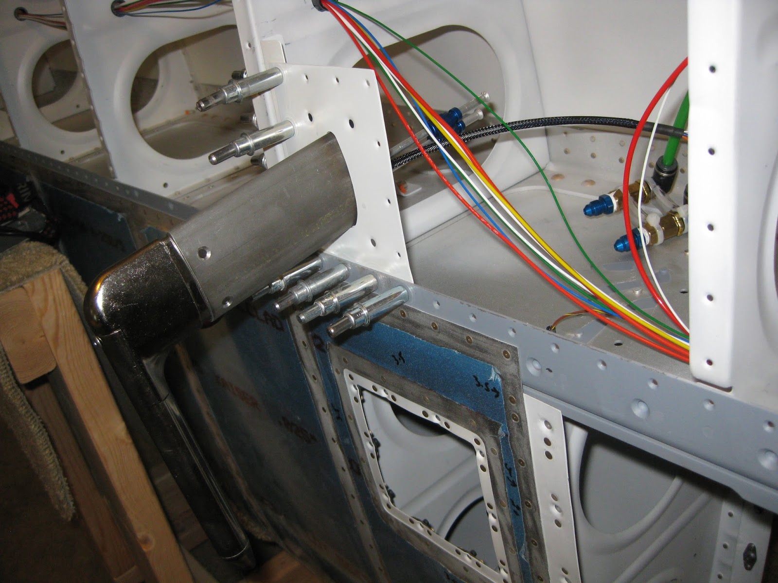


For the curious, the little gray spots on the spar webbing are areas that were scratched during leading edge installation that I later sanded out and primed. Also, the red and white wires that seem to curl off to the right are the Dynon pitot heater and status light wires I strung earlier. They're just pushed out of the way for now. You can also see the extra wires I added for my landing lights. More on that in a later post.
I also decided to countersink the PBK-12 Gretz Aero bracket after match-drilling and tapping the holes in the probe. Because the bracket surface is curved, I c'sunk by hand with a deburring bit, very slowly.


Off to the right side...A 7/16" hole was needed for the right wing pitot (following removal of the rivet that was originally there). The plans call for this to be done on the left wing, of course. But that's where the Dynon heated pitot will be. What's interesting is how little leading edge skin remains on the aft side after that hole is drilled. Prior to mounting the hardware, this will need to be primed.

Here's the right pitot hung with and without the cover. I used the kit's clear tubing for the right side pitot to help differentiate it later at the panel.


You can see some
Read the entries in my AOA series:
No comments:
Post a Comment