Showing posts with label 33 Rudder and Brake Systems. Show all posts

23 December 2017

Modification: Rudder pedal springs.

My right brake liked to stick.  It meant dragging the left brake sometimes to keep the aircraft straight on the ground.  Plus, it made using the tow bar a real workout.  Many folks use return springs on the master cylinders to mitigate this problem.

So off to the local Ace Hardware store for some Hillman, item #115, 5"x5/8"x0.042" (~3 TPI) springs at $1.15 each (I tried other spring sizes but those worked best).  About an hour of my time under the panel and problem was solved.

Right seat pedals.


Left seat pedals.  That little air bubble in the line appeared after I thought I got them all back when I filled the brake lines in October of 2016.  I can't get it out but it doesn't seem to affect braking meaningfully.


09 October 2017

Fuselage: Rudder and Brake Systems. Longer rudder cable links.

I have given away all of the extra sets I had.  If you need a set, download the CAD drawing (consider updating the spacing as I explain below) and buy the steel stock material.  Links to both are provided in this post.

When I push the left pedal forward (which of course simultaneously pulls the right pedal aft), the "ear" on the WD-655-R pedal frame contacts the horizontal tube of the WD-655-L pedal, preventing the rudder from hitting its left stop.  My pedals are in the forward-most position (closest to the firewall).  This happens even with the proper rudder travel.

Below illustrates where the contact occurs as the right pedal is pulled aft and the left pedal pushed forward.  You can see where the powder coating came off due to the contact.


It appears as though the CS-00015 Cable Links need to be just slightly longer so that the cable need not be pulled forward so far (page 33-12).  Or, alternatively, that the CS-00014 Rudder Cable needs to be slightly shorter.  The latter solution is not practical.  I consulted with Van's and they suggested fabricating longer Cable Links or reducing the rudder throw.  However, to accomplish the latter would excessively limit the throw, so I deemed it undesirable.


So I bought some inexpensive 0.05" 4130 steel stock (the same material and thickness that the kit's links are composed of) and whipped up new cable links in my CAD program (LibreCAD - free is good).  I added two additional holes in comparison to the original cable links, giving me 9 holes rather than seven.  I went ahead and dropped four full sets on there since the waterjet shop was going to charge me the shop minimum of $75 for the small job. 


Ultimately, the waterjet shop said they'd make as many as my material would permit.  That turned out to be 18 Cable Links, so 4.5 sets.  Below shows the links.  The top row are 14 links as they came from the shop (dirty, rusty and undersized holes).  The bottom row shows one of the kit's Cable Links, followed by two sets of the longer links after final drilling to #12, deburring, sanding and cleaning for painting.


Installed, following painting.


If you need to fabricate your own, below are the final dimensions (ream to final size).  These line up very well with the original, shorter cable links.  Also, here is the dxf file with 16 links (the hole diameters are undersized by 1/64" and the width of the links are 0.04" wider to account for waterjet tolerance).
  • Holes are #12, so 0.189" diameter.
  • The first hole is centered 1/4" from the edge.
  • The second hole is center-to-center 0.75" from the first hole.
  • Subsequent holes are spaced 11/32" (0.34375") center-to-center.
    • I think the holes on the original parts are spaced 0.3445" center-to-center.  That would place exactly 1/4" from the hole edge to next hole's center.
  • The edges are half circles with a 0.25" radius, centered with the adjacent hole.
A picture probably expresses that much more clearly.

10 October 2015

Fuselage: Rudder and brake systems. Completed.

The rudder pedal assemblies took some time to get right.  The fitting of the correct washers and bolt tightness is a never ending back-and-forth, remove-and-redo game.  Eventually, it comes out right.


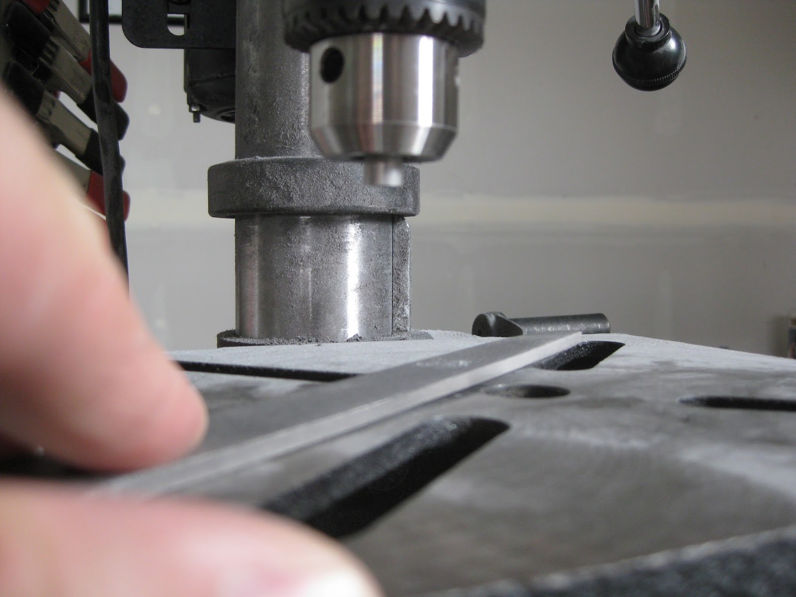
As an aside, the spacers from page 33-03 are difficult to cut straight.  I tried multiple times and just couldn't do it on my band saw.  Whilst I'm sure I'm not the first amateur machinist to devise this approach, here's what I came up with:  I cut the spacers intentionally too large, then chucked them into my drill press and brought them down on a file on both sides of the spacer until each was perfectly flat and just the right size.  I tried to get a picture of this, but the camera refused to focus on the subject, instead opting for the uninteresting background.  My apologies for the poor quality.


Installation of the assembly into the fuselage is quite easy, however you really have to pay attention to avoid over-torquing the nuts.  The balance between friction and free-play is made quite clear in the plans.  


The rudder cable guides took several hours to install.  It's nearly impossible to get access to the nuts and bolts and frustration was abound.  Here's how I ultimately secured the nuts:  First I positioned my wrench to work against the opposing bolt (left), then taped it down so it wouldn't fall when I was torquing the other side (right).


Eventually, each side gets done.  Left side shown below.


I think it's worth routing the rudder cables to the front of the aircraft prior to installing the baggage floors in Section 32.  It's still doable in Section 33, but it's much easier without the floors.  Anyway, I decided to prime and paint the cable CS-00015 cable links black to give them some contrast against the rest of the interior (cotter pins were not bent in this image).


The lines themselves are easy enough to cut, prepare and install.  The boiling water technique explained in Section 5-29 is very helpful to push the brass insert entirely into the tubing.  Boiling water?  Yep.  I love the varied building techniques used in this project!


Completed (I didn't finish the brake line routing until after I had installed parts from Section 35 as I was waiting for a #29 drill bit, hence the reason this image wouldn't match the end of Section 33).

03 February 2015

Fuselage: Rudder and brake systems. Rudder pedals.

Not only am I out of space, the weather is not conducive to priming.  So I progress through the plans, match/final drilling, deburring, etc., collecting a large pile or prepared aluminum awaiting a turn through the priming process once the snow departs and the sun returns.

To that end, I got to cleco'ing the rudder pedals together for match drilling on 26-Dec-14.  They feel mighty stout.


After seeing this guy's pedals, I decided to paint my pedals red using Rust-Oluem Painter's Touch poppy red satin finish from Airplane Depot.  I finally got around to that on 27-Jan-15.  The parts looked nice once painted, after scuffing and acid etching (yes, the instrument panel frame in-progress is front-and-center - working ahead to make use of the time and space as best I can).


And here are the completed left side rudder pedals and one right pedal (the other needs repainting since I dropped it and ruined the finish, thankfully before any riveting).  Not sure I like the gold-on-red at the rivets, but no one will care, other than me, apparently.  Because all of the rivets are universal head or LP4-3, the squeezer/puller doesn't upset any of the paint.  Hopefully the paint will hold up because I doubt they'll ever be repainted once installed.


The right, right rudder pedal's paint was easily removed after soaking it in acetone for 6 hours.  The paint mostly sloughed off on its own during the soak.  What remained was easily removed with an acetone-moist cloth.


It's interesting to note that the prototype RV-14A, N214VA, has a different set of pedals on each side.  The left side (left) has the same pedals as included in the kit.  The right side (right) has pedals from what seems like their other models (I took these pics back when I visited Van's).