Showing posts with label Maintenance. Show all posts

17 May 2025

Maintenance: Airflow Systems 2007X oil cooler failure in flight.

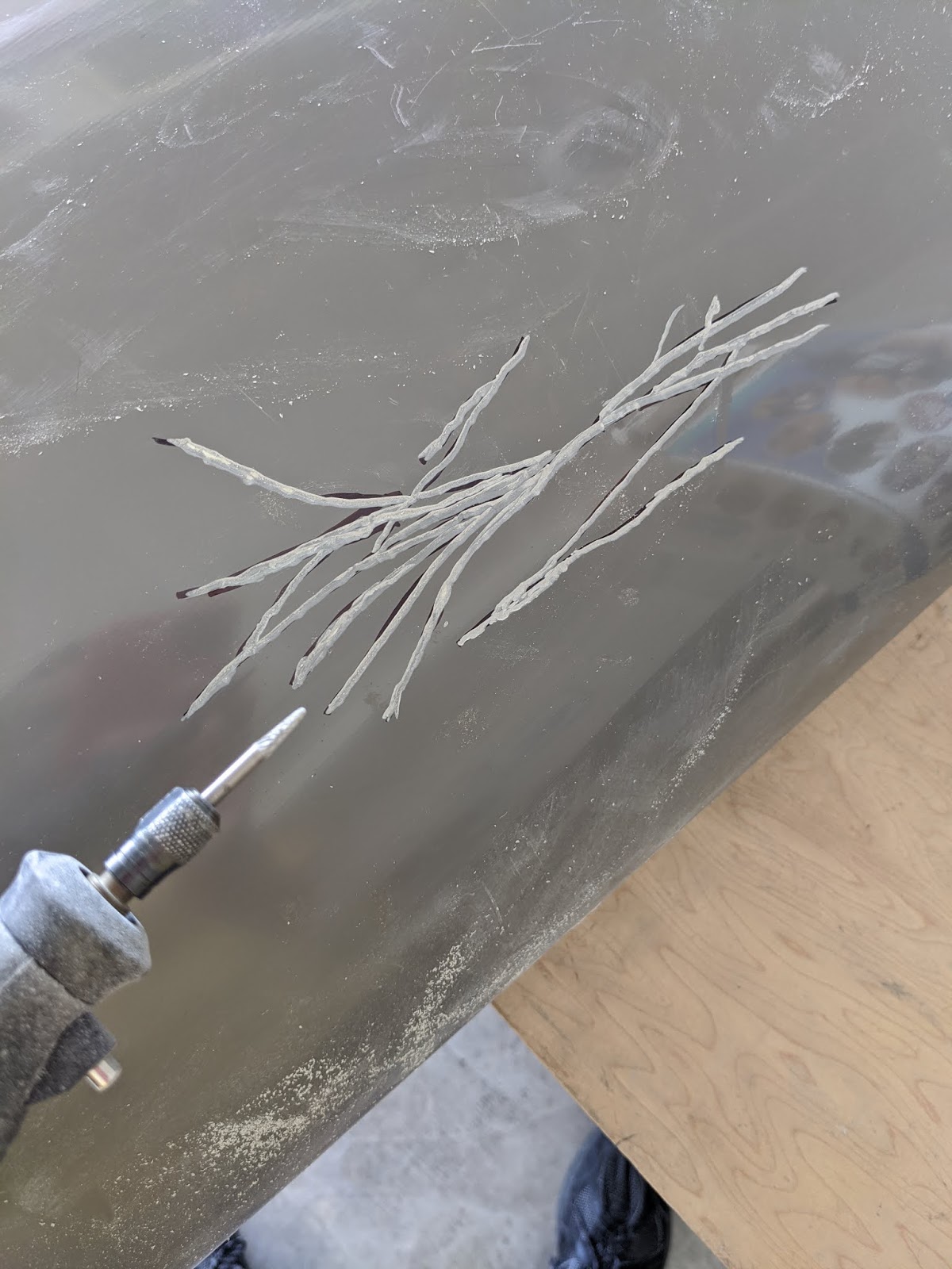
On 14-May-25, my Airflow Systems 2007X oil cooler failed in flight with only 75.9 hours on the cooler.  In just a few minutes of flight, it ejected almost 60% of the engine's oil, leaving me about 2.25 quarts in the sump at shutdown.  Thankfully the failure happened just as I was about to enter the downwind for landing at my home drome.  Below shows where the Airflow Systems 2007X cooler failed, just above the red line.  

That seam opened up right at the intake side of the oil cooler.  The oil sprayed against the firewall and the airflow carried the oil out the right exhaust exit of the cowl, coating the belly of the aircraft with oil, as shown below.  You can see how the oil almost entirely favored collecting on the right side of the airfame.  And yes, it was a mess to clean up the airframe.  

Everything under the cowl was remarkably entirely free of oil save for a little splash on the firewall behind the cooler where the spray departed the failed 2007X cooler.  In fact, it was difficult for me to find the location of the failure until I pulled the cooler out of the plane and pressurized it.

The incident in flight manifested as a drop of several PSI of OilP and a momentary increase in prop RPM to 2710.  Both of which my GRT EFIS caught and annunciated by voice.  

Below shows the OilP in flight.  The x-axis is minutes since engine start.  The red arrow indicates when the OilP became unstable, most certainly indicating when the Airflow Systems 2007X oil cooler failed.  OilP goes to zero on the graph since the engine was shutdown with the EFIS still on.

Why do I have the 2007X rather than the stock 2006X?  I fly behind an IO-390-EXP119.  Read here to learn why high summer OilT led me to install a larger cooler.  

Turns out that the 2006X has a service bulletin (curiously, they no longer have that document on their website so I have it available here and Van's has a reference to it as well here on Vans' website).  Airflow Systems' document states that a specific swath of serial numbers had a potential manufacturing defect that could lead to a leak from the vanes or core area of the cooler.  Whereas Vans' document also reiterates the need to use a "double wrench" method to tighten fittings on the cooler.  Interestingly, Airflow Systems didn't issue a service bulletin for their other models.  I point that out since Airflow Systems uses the stacked "drawn cup" oil cooler design.  I'd be interested to learn why the issue they identified was limited to the 2006X.

There are several reports of the 2006X failing on RV-14s (example here).  In fact, Van's has an online form seeking to collect that information.  In my case, I did use the double wrench method and the intake hose was constrained by Adel clamps to the engine mount where the outflow hose was constrained by wire ties.  My prop was not balanced during the time the failed 2007X oil cooler was installed and was measured at 0.2 ips vibration following the oil cooler failure.

Below, I show Figure 2 from plans page 49-13 that illustrates how the oil intake hose is routed into the cooler (traced with a red line).  You can see that it enters the cooler with a 90 degree fitting and is generally unconstrained over a significant length.  This may be a source of unwanted vibration being transmitted into the cooler.  I wonder why they didn't bring that hose in directly by going behind the engine mount.  Maybe it was to reduce the parts count for the airframe (relative to tail dragger vs. nose dragger) or to allow the hose to have enough slack to accommodate movement of the engine during startup and shutdown.


For what became my failed Airflow Systems 2007X cooler, I took a similar route and constrained the hose to the engine mount with a pair of Adels (the latter of which is circled).  Perhaps the hose routing caused some torquing of the fitting and transmitted unwanted vibration into the cooler.  The fittings were clocked slightly differently than for the stock 2006X since the failed 2007X is slightly longer so the hoses are slightly too long.

I reached out to Airflow Systems to have a conversation to help me understand why this happened, whether it was my fault (hey, whatever skills I have, it isn't in aircraft development), a kit design issue (e.g., hose routing problem) or a manufacturing issue.  Suffice it is to say, my interaction with the Airflow Systems rep on 21-May-25 was very disappointing.  Those details aside, they did said they'd try to get me an RMA to return it to the manufacturer (which is in PA, not CA where the company is located) for analysis.  Despite some follow-ups on my part, I'm simply told that they are "working on it" and thus I haven't received an RMA (as of 3-Nov-25, nearly six months after contacting them).  This indicates to me that they aren't serious about understanding why one of their products failed.  I was also told that my cooler is "way outside of warranty" (having purchased it ~18 months before and installed it just short of a year ago) and despite that, they would sell me a cooler "at cost".  Replacing the cooler with the same model (even at no cost) was not a satisfactory remedy to me since the root cause of the failure remained unknown.  Getting the cooler back to the manufacturer for analysis was important to me.  It appears it isn't important to them.

My oil cooler details:

  • Manufacturer:  Airflow Systems 
  • Model:  2007X
  • Serial number:   E22-15691-09
  • Purchased:  7-Dec-23 
  • Installed:  29-May-24
  • Failure:
    • Hours of flight:  75.9 
    • Date:  17-May-25 

The inadequate customer service found me having little confidence in Airflow Systems.  At that point, I sought to find other alternatives.

It's worth reading this great Kitplanes article explaining how oil coolers are made.  Airflow Systems uses what seems to be the more fragile, less expensive and stackable "drawn cup" design whereas Aero-Classics has models using the more stout and more expensive "bar and plate" design in many of the PMA'd coolers.   

I reached out to Aero Classics.  I had a refreshingly helpful conversation with them and was put in touch with one of their engineers.  This catalyzed a wonderful dialog about their oil coolers' performance and what might be a good alternative for me (including a discussion with heat rejection vs. airflow plots).  I came away from the interaction impressed with their drive, knowledge and willingness to help.  They even provided me a 3D CAD model of the cooler (below) we selected, so that I could verify my tray and duct design for the new setup!  It was indeed a night-and-day difference when compared with the uninspiring interaction with Airflow Systems.


Following that conversation, we together thought that the HE 8001652 model (the "HE" indicates high efficiency) would be a good alternative for me.  

It's a 13-row "bar and plate" design, as shown below.  In mid June 2025 at Aircraft Spruce, the 2007X costs $973 whereas the 8001652 costs $1,295, so almost exactly 1/3rd more.  Even though the 8001652 has two fewer rows than the failed 2007X, the dimensions of the rows and fin densities are different than that of the failed 2007X, so comparing the coolers on  the basis of the number of rows is inadequate.  Additionally, the engineer felt that the 8001652 has a better sealing interface that would mitigate air leakage around the core.  I will defer to their expertise since whatever expertise I may purport to have (surely, dubious claims on my part), it isn't that.


Quick calculations showing the cross-sectional areas and core volumes of the 2006X, failed 2007X and the proposed 8001652 are below.  Whilst the cross-sectional area of the 8001652 is about 10% greater than that of the failed 2007X, the volume of the core is actually 2.3% less since the core width is 3.2" rather than 3.62"

Yet, it turns out that this cooler was horribly inadequate.  You can read about the installation of this cooler in my airframe and the cooler that I ultimately chose to replace my failed 2007X.

20 February 2024

Maintenance: Crankshaft seal failure and replacement.

Following a night of practicing approaches, I dutifully put the plane back in the hangar.  The next morning I went back out to the hangar to replace the EGT4 sensor which had stopped functioning.  When I looked at the plane, I saw that my engine seemed to have burped oil overnight.  Based on the oil drip paths, it seems not to have happened in flight or even on the ground during taxi.  At this point, the aircraft had 411 hours.


Viewing the aft side of the ring gear found oil of course, but also some kind of flexible material that I later determined was some cured sealant holding the crankcase in, perhaps showing the source of the failure. 

Now it was time to learn how to remove and replace the crankshaft seal.  Lycoming has a service instruction for that (1324D).  Removal of my crankshaft seal (which of course requires removal of the propeller), showed sealant missing in the grooves, though that sealant may have detached during removal.

Installation of the replacement seal requires a special tool.  Lycoming has one for more nearly $2kATS has one for just over $100, so I went the latter option.  I didn't capture images when I was using the tool since it requires two hands and I was working solo.  I did grab a snap when the seal was in place and also when I was pushing the spring in with a bike tube replacement tool (prior to application of Dow Corning 737).  It also made sense to replace the alternator belt (a Dayco 15355), though the original one had no signs of wear on it that I could see.

Following reinstall of the prop and a ground test, the new crankshaft seal has been functioning properly.  So that was an interesting experience.


20 November 2020

Maintenance: Third annual condition inspection.

Time for the third annual condition inspection (here are the first and the second) at 230.8 hours (see here for my POH, W&B, flight and annual checklists and flight test cards) and 1,611 gallons of avgas burned.  The annual took nearly 40 hours over 3 weekends.  A number of interesting findings turned up, as outlined below.


Oil leak:  Found some oil that I hadn't seen before...


I believe it's coming from where cylinder #1 mates to the crankcase.  Knowledgeable folks advise me not to worry about it and to keep an eye on it.


Nosewheel breakout force:  During my first condition inspection in 2018, I could get either 17 or 42 pounds on the nosewheel breakout force (see page 40A-07) due to the cotter pin alignment.  It's supposed to be 26 (which it was prior to first flight).  It escaped me (despite it being clearly written in the plans) that one can drill a new hole in the U-01406 Nose Gear Leg to accommodate a greater range for breakout forces.  So I drilled a new hole 90 degrees from the existing hole (shown below following drilling and test fit of cotter pin).  And magically, I got exactly 26.7 pounds on the breakout force (with new grease in the fitting).

Brakes:  They drag ever so slightly.  Back in December 2017, I did the canonical spring modification.  But, you could still hear the brakes drag when pulling the plane out of the hangar and even a bit of squealing when taxiing.  Long story short, I pulled off the caliper assemblies, cleaned up the pins then lubricated them with LPS-2.  However, what I believe was most important was to reposition the brake line so it wasn't torquing the assembly.  The assembly now slides a lot easier (following flight after this inspection, it appears to have solved the issue).   I went ahead and replaced the left wheel's brake pads (the right's were changed in 2019).  They didn't need to be, but I felt better getting them replaced now so they match the right side's more closely.

Wheels:  Both main tires replaced (the nose's is fine).  They were rotated in 2019.  The left one needed to be replaced.  The right one could have kept going.  I will monitor the wear more closely this time and if it continues to be asymmetric, I may consider shimming one of the axles.  Or maybe it's just bad piloting skills.

Elevator idler pulley:  I noticed a little bit of slop here.  When I pulled the bearing's bolt out, I found it was an AN4-12A.  It should have been an AN4-11A (per 36-02).  Oops.  Probably not going to bring the bird down, but it sure makes one wonder what else I missed.


Alternator filter:  I was proud of myself for figuring out what I thought was an elegant install.  It wasn't.  Turns out that the metal hood that I bolted the filter to could not be recruited into the task of holding this relatively heavy filter in the punishing environment of an IO-390.  I'm quite fortunate that the filter didn't completely separate from the airframe and depart the cowl in flight, doing damage to something or injuring someone.  This was a very educative experience and a potent reminder to stay within the bounds of my knowledge:  Don't do something that hasn't already been shown to be safe.

Fuel filter leak: I was pleased to see that my fuel filter was quite clean (left).  However, I was not pleased to see that there was another fuel leak in that area (right).  At last year's condition inspection, the fuel pump leaked due to the way it's constructed and how torque applied to its fittings is carried through its body.  See this post for information.  During this inspection, when I opened the inspection cover and saw the leak, I was amazed that I never smelled it since last time, it was the odor of fuel on opening the canopy that led me to find the original leak.  

I believe what may have happened is that the thread sealant on the NPT fitting between the filter and pump wasn't fully cured before flying.  So the leak happened only once and I never smelled it since the odor went away.  I could be wrong on that assessment.  I will be opening the inspection plate after the first post-inspection flight to try to verify.


Wing gap fairings, pan head to flush: Curiously, the plans specify that the 7 aft-most screws for the F-1411B Lower Wing Root Fairings should be pan head screws, as clearly evidenced in the following images from the plans (41-05, 41-04 and 29-18, respectively).  With the plane finally assembled back in 2017, I couldn't understand why those screws were specified as pan heads.  Yet, if you look very closely as Figure 3 on page 29-18 (not shown below), you can see that the protoype used K1100 flush nutplates (rather than the K1000 called for in plans).  So I decided to swap mine out to go flush.


The three aft-most nutplates could easily be removed from under the aircraft.  The second and third one back were more easily removed from the top using 12" long bits at a deliberate angle.  The fore-most nutplate was removable from below, however the wing spar is along the trajectory of the drill bit so I used a spring drill stop to prevent a catastrophe.  It was easy to dimple the skins using a screw with lots of Boelube on its head by just screwing it into the nutplate until it offered resistance.

Here are my replaced nutplates.  In the left image, you're looking down the gap with the wing on the left and fuselage on right).  The nutplate under the wing spar could not have its rivets squeezed or bucked due to the wing spar, so I used CCR-264SS-3-2 (right image looking inboard from the bottom of the left wing).


Now the Lower Wing Fairings are nice and flush (don't mind the in-process RV-14A tail in the background) so I'll get my 0.01 KIAS back.


Clean belly: My belly was an oil slick.  Now it's clean (can't say the same for the nosewheel fairing).

Engine borescope: Piston, cylinder wall, exhaust and intake valves of cylinder #1 shown.  All looked fine for this and the other cylinders.


Spark plug insulators broken:  Upon pulling the plugs for cleaning and gapping, I was greeted with broken insulators on #1T, #1B, #3B and #4T (top right, top left, bottom right, bottom left, respectively).

This caused quite a learning episode (experimental aviation is supposed to be for education right?).  This is evidence of detonation (not pre-ignition).  Using my comprehensive data analysis program, I combed all the engine data from every flight since my last condition inspection (which was the last time the plugs were serviced).  I was looking for any indication of a runaway CHT.  I could find none.  

I called Lycoming's technical support and was immediately in touch with a great technician (who ironically signed my engine's test run sheet at the factory in 2015!).  We had a one-hour long conversation whereupon we discussed how the engine was operating, how I was operating the engine, I sent him pics of the plugs, the borescope pics, the oil leakage and the fuel servo cable rigging.  We went over some performance numbers of the engine on takeoff and found that I was consistently running 4 to 5 GPH lean!

The technician offered several things to check:  Fuel restrictions (kinks in fuel hoses, verifying fuel flow through injectors), verifying mixture arm hits the stops and finally checking that the fuel servo is flowing properly.  We also discussed my approach to leaning for takeoff:  Slowly lean mixture until rough, then richen two or three turns (an approach I've used in every aircraft I've flown - which is a whopping 4 different models).  He indicated that that was the correct approach.  So I came away from that call thinking, perhaps erroneously, that my fuel servo might need to be recalibrated.  

The technician didn't see any evidence of severe detonation (e.g., clean pistons) in the borescope pictures. He advised to fly the airplane and not be concerned with possible damage.

After replacing all of the spark plugs to the tune of nearly $300 (!), and learning about fine wire vs. massive, my plan was to richen the mixture on takeoff until I hit a target flow rate appropriate to the altitude here (calculable from Figures 3-2 and 3-3 in the IO-390 operations manual).  If I couldn't get the correct flow, I'd abort the takeoff and pull the servo for servicing.   A friend advised that I change my leaning process for takeoff to instead lean until the first cylinder's EGT peaks, then richen to 100 degrees ROP.  The IO-390 manual states to go full rich for takeoff and only lean it out if it runs rough (e.g., at a high altitude airport - like mine).

I do believe I know when the detonation occurred.  My flight review was last month and we did a number of simulated engine outs when it was relatively hot outside.  The engine was worked probably harder than it ever has been.  Thus, the CHTs were relatively warm on those takeoffs and being fuel-starved and lean, conditions were probably good for detonation.  Though again, nothing in the engine data evidenced detonation on that day.  Turns out, detonation can be utterly transparent to the pilot and within the engine data.

Finally, after 3 weeks, the aircraft was buttoned up and ready for flight.

I was able to get the proper flow rate on takeoff.  I still need to compare with other RV-14A owners here in the area to see where their mixture is set for takeoff to see if perhaps my servo needs adjustment.  The brakes don't drag and since the nosewheel breakout force isn't overset, the aircraft is much more compliant on the ground.

That is one clean belly.


21 May 2020

Maintenance: Fix cracks on wing tips.

Following about 170 hours or so on the airframe, I noticed that my wing tips were cracking around where the rivets for the nutplates were.  Though I used "soft" rivets for those and took care not to over squash them with the squeezer, it seems that didn't help mitigate what ultimately happened.  

Plus, back in 2016, I dropped one of the tips in the kitchen, which caused a very large cracked area as well as two others.  Below shows the larger cracked area.


So I removed the tips from the plane and brought them home.  My plan was to drill out all of the nutplates, bond in an additional layup of fabric and install new nutplates.  Then I could fix the gelcoat cracks.

To make my life easier, after removal of the nutplates, I inserted screws into the holes and taped off the holes.  This way my new nutplates could be aligned to the right locations and the epoxy from the layup wouldn't push out further than the flange of the wing tip (left).  In the right image, you can see a layup applied with peel-ply.  It didn't have to look pretty, since it's on the inside.  It just needed to serve its purpose.


With the peel-ply removed (left), there was some filing work to do (right), then drilling and countersinking for the new nutplates.


Next it was time to fix all the cracks.  I marked where the cracks were with a marker (left), then removed the gelcoat down to the original layups with the Dremel (right).


I used Evercoat polyester gel paste, which is appropriate for the material composition of the wing tips. 


It's a two part affair (left) and a surprisingly aggressive exothermic reaction upon mixture (right).


After working it into the cracks, I applied wax paper to get a smoother finish (left).  Removal of the wax paper demonstrates the hours of required finishing by sanding (right).


Following sanding, it came out pretty good (I neglected to take pictures of the areas at the nutplate rivets).  I used 80 grit to get it close, then 200 to get level, then 400 and 600 to get a nice sheen.


Installed on the aircraft, the "injury" to the tips is apparent, however when painted it will be unnoticeable.


I actually did three attempts at fixing the bigger crack (always seems to take more than one try to do anything with this plane).  Here's the final result.  Running your hand over it, that there was a crack is imperceptible.