Showing posts with label 22 Ailerons. Show all posts

10 November 2013

Wings: Ailerons. Left aileron mounted.

The left wing continues to grow in size and weight.  The left aileron has been mounted.  A welcome respite from the recent challenges.


In this position, the aileron naturally rests against the stop on the inboard hinge.


As is, there's nothing preventing the aileron from over-travel in the downward deflection.  That over-limit protection is provided when the pushrods are connected so the stop on one aileron prevents over-travel of both.

09 November 2013

Wings: Ailerons. Complete and an important lesson learned.

Completed the ailerons today. 


A bit of a story here though.

Last week, I attempted completing the trailing edge of the left aileron only.  I very carefully calibrated the countersinks in the wedge to allow the skins to sit flush.  About ten fully-driven rivets in, I gave up as the same problem I was having with the flaps was presenting itself to an even worse degree.  Specifically, the dimples on the bottom (shop head) side were collapsing into the wedge countersinks, providing a very poor finish.  I tried a) classic backriveting, b) the mushroom set and c) even using the mushroom set itself banging on a steel plate, thinking I could avoid the dimple collapse.  No joy.  Time to remove the wedge and try something else.

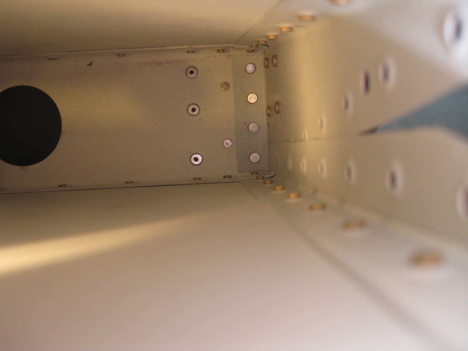
With pliers, I easily pulled out all the rivets that I lightly tapped in with the backrivet set.  But the other ten fully-driven ones required more deliberate removal, causing some messed up holes (since there are three separate pieces each with their own independent planarity, it's not an easy task, plus any force applied to the trailing edge can bend the constituents).  Oh well, at least they're messed up on the bottom rather than the top (poor quality image below).  A chip chaser let me separate the wedge from the skins given they were taped in.


In an attempt to solve the issue I consulted a very knowledgeable tech counselor.  It was the first time he'd seen the issue.  He thought the countersinks might be too deep.  I consulted an A&P friend of mine.  He thought the same thing.  But I didn't think that could be it since I calibrated the countersinks against a scrap piece of wedge to make sure the skins sat flush.  And if they were too deep, why was I getting a large gap between the wedge and skins?  That didn't make sense to me.  

Concurrent to all of this, I had shot an email to Van's about the flaps issue and Sterling replied that he thought the countersinks might be too deep and that my edge break might not be aggressive enough...Wait, edge break?  Uh oh.  I didn't do that.  The plans don't call for that on the flaps (yet, they should), but they do for the ailerons.  In the case of the latter, I was too concerned that, without a metal brake, I would really jack up the aileron trailing edges (these aren't nose skins or skins sitting underneath other skins like elsewhere).  Besides, wouldn't the riveting process compress everything together rendering that step moot?  

Making an edge break was not an option now that the dimples were in place on the skins and the skins were on the spar.  So, for the wedges (replacement on the left aileron, first try on the right) I reduced the depth of the countersinks:  7 clicks beyond a flush rivet for the left aileron and only 5 for the right.  The dimples still compressed into the countersinks (I redid the left first, hence the shallower depth on the right). 


And I do have ridiculously large gaps between the skins and wedge.  Not much to do about it now, other than to reduce the countersink depth on the empennage surfaces and actually make the edge breaks.  I believe it was the riveting process that caused the skin edge to lift away from the wedge and introduce the unsightly gap.  The edge break would have eliminated, if not mitigated, that problem.


Here's a comparison of the countersink depths used on the wedges.  The bottom wedge shows the original depth I had on my first attempt after calibrating to skin flushness.  The top shows 7 clicks beyond a flush rivet.  Big difference.  Yet both depths permitted the skins to sit flush against the wedge, so clearly I went too deep initially. 


The edges of the ailerons are reasonably, though not acceptably, straight.  The right side has a distinct curve to it that I'll have to bend out.  The left side is mostly fine but there are a few places I could fiddle with to straighten it out better.


Be careful using a backrivet set.  It's very easy to dent the skin.  See below:  Upper left of lightly tapped rivet has a dent from the backrivet set's collar.  And when using a mushroom set, it's very easy to mash the wedge out of true.  Just can't win!


Other issues:  Significant oil-canning on the bottom skins.  It's probably related to there being stiffeners rather than ribs.  Also, many of the top rivets on the left aileron aren't fully flush.  Since the right side is fine and my technique was the same, I suspect it might be related to the tape residue that remained when I pulled out the first wedge on the left aileron.  Example of the worst rivet on the left is below.


So, lesson learned.  Edge break trailing edges and be cautious on the countersink depth.  I'm not at all pleased with how the aileron trailing edges turned out.  But it's time to get over it and move on.  Perfection, whilst an admirable goal, isn't going to be realized on this build.  How to feel like an idiot:  Build an airplane.

28 October 2013

Wings: Ailerons. Bottom skins on.

Bottom skins are on the ailerons.  Trailing edge wedges and lateral rib riveting remains.  Below images have left on left and right on right.


I used AN426AD3-4 rivets on the lateral-most holes.  This is where the nose skin, spar and main ribs' tabs mate.  The AD3-3.5 called out in the plans are too short, as I determined when doing the analogous holes on the top skins.  When using a AD3-3.5 on the bottom skins, you risk the rivet not catching the rib's tab, making life very difficult (this is because, in order to get your hand on the bucking bar resting on the spar, you need to pull the bottom skin out, which positions the tab off the rivet).  I drilled out a rivet four times before I decided to up the length to an AD3-4.  Below is the left aileron inboard side with the bottom on the bottom.  The bottom inboard-most rivet is AD3-4 whilst the top inboard-most rivet is AD3-3.5.


For the inboard-most spar-nose skin rivet, I used the back rivet set to hit the manufactured head.  This is because the overlapping bottom skin immediately adjacent creates a standoff that prevents you from getting the rivet flush if you use a mushroom set.


The plans warn against letting the bucking bar drive into the stiffeners of the bottom skin, so be mindful of your bucking bar size and test its fit before use.  Mine just cleared the stiffeners, so I had no issues.


I calibrated my gun's air pressure so two half-second hits would completely set each rivet.  When riveting, placing the mushroom set so it also just overlaps the joint between the skins helps smash the skins down and eliminates pillowing between rivets.  I ended up with awesome, gap-free seams.


27 October 2013

Wings: Ailerons. Outboard rib-to-spar riveted.

As I mentioned previously, the outboard rib-to-spar rivets are extremely difficult to access (Update 31-Mar-20, see below): .  With the manufactured heads on the spar, the face of your rivet set is too large to seat on the universal rivet's head properly.  Conversely, with the shop head on the spar, you need a very narrow bucking bar to get into the space between the outboard hinge brackets A-1006-1A and A-1006-1B (in fact, you're better off not riveting A-1006-1B to the main rib until after bucking the rib to the spar, which is contrary to plans).


Measuring the space between the outboard hinge brackets yields it to be precisely 0.5".  Turns out, I have a bucking bar with just that width.  Admittedly, it's poorly shaped for the task and fairly light to be bucking AD4 rivets, however I managed just fine with some planning. 


Covering it with tape to prevent it from marring and removing the primer from the inside of the outboard hinge brackets, I was able to push it in to meet the shop head of the AN470AD4-4 rivets (the top-most rivet was instead easily buckable with the tungsten (wolfram) bucking bar as the taper of the brackets meant access was no longer impeded at that rivet).   Here it is seemingly floating as the friction presented by the brackets hold it in place.


Then I used my 10.5" long straight 1/8" rivet set to clear the length of the top skin. 


An example of how everything lines up is shown below.  Obviously, I need to hold the bucking bar when actually riveting.


You can see here how awkward this approach is below.  It took planning, rehearsing and great care to make sure the bucking bar wouldn't slip (even with all the friction holding it between the brackets, the violence of riveting moves the bar around and in doing so it can contact and ruin the shop heads of the set rivets previously completed) and that I wouldn't lose control of the rivet gun with the leverage inherent in using that long 10.5" set.


I would have been better off with a 13" long set since I was forced to put a slight smile into the rib flange at the top-most rivet.  This was due to the 10.5" set requiring a very subtle angle to clear the skin.  This is even after I removed the spring from the gun to give more clearance.  However, the minimal marring was sanded out and spot primed over.  Below are the manufactured heads with the slight smile on the rib flange sanded out, prior to spot priming over the area.


Here are the shop heads.  The primer around the heads flaked off following expansion of the spar.  This has actually been a very rare occurrence in the build overall.


Excellent.  On to riveting the bottom skin to the spar, then the trailing edge wedge.  Need to get the latter right this time as it didn't go well last time.

Update 31-Mar-20:  Six-and-a-half years later, I decided to build another set of ailerons since I wasn't happy with how the trailing edges of the set came out.  As part of having accumulated experience in construction, there is another way to buck the rivets outlined in the post above such that the manufactured heads are on the outside.  See below.


 Grind down a side of an offset rivet set (the tape is to prevent marring of the aileron).


Now the manufactured heads will be on the outside.

26 October 2013

Wings: Ailerons. Nose and top skins on spar.

The nose and top skins are riveted to the spar on both ailerons.  Fairly straight-forward process.  Some rivets holding the nose skin to the nose ribs are blinds (MK-319-BS).  Though a squeezer can fit with the right yoke, I believe the skin curvature is excessive for the squeezer sets to accommodate, hence the blinds.  Anyway, after completing all skin-to-rib rivets, I noticed this unfortunate occurrence on both inboard ribs.  Yes, if you look closely, a rivet is set in there, it just moved the tab out of the way.  That's no good.


Here was an opportunity to learn how to remove pop rivets.  Turns out, it's fairly simple (at least, if you can access its "shop head" side).  First, tap the mandrel out of the body (see image below), then hold the body with a needle-nose (to prevent spinning) and drill to remove the head.  Finally, yoink the "shop head" side out with the needle-nose.


Below is the replacement rivet with the tab properly positioned (compare to very top image).  This required one hand to push the tab against the skin (after all, it was bent out), one hand to drive the pop rivet tool and my chin on the tool's head to push the rivet's head down flush.  Good times.


Here are the ailerons setup for riveting their top skins and spars.  The astute will note the fuel tanks directly behind and the flaps in the way background to the left.


Here are the ailerons with their top skins riveted to the spar.  The right side is in the foreground.  The  tungsten (wolfram) bucking bar makes this so easy.  In fact, did both top skins in 47 minutes.


I'm trying to solve how to set the rivets shown below.  A post with the associated solution will follow.  For now, I believe that part A-1006-1B (outboard hinge bracket) should not be riveted on the outboard rib until after the A-1005A ribs are riveted to the spar.  This is contrary to plans, however that bracket seriously impedes access to the AN470AD4-4 rivets and that bracket can be easily squeezed-riveted after the skins are in place.


21 October 2013

Wings: Ailerons. Temporary assembly.

Ailerons were temporarily assembled to check for a straight noseskin.  Here is the left aileron with top skin on.


Checking for noseskin bowing, left and right sides.  Didn't find any.  Note, the ruler on the right side is misaligned on the outboard edge in the image.


Right aileron, top and bottom sides.  Trailing edge wedge not yet cut to size.


Here's the tool I used to ensure the angle on the trailing edge wedge holes was perpendicular to the aileron's chord.  This was a design from the control surface practice project.  It's a small piece of wood with an 84 degree cut from the miter saw.  The length of the drill bit is rested on its surface to hold the angle.  On the left image, the astute will notice that I'm holding it incorrectly in the demonstration image (the proper 84 degree angle is marked on the piece as shown).  The right image is another posed one where I taped the tool to the skin for demonstrative purposes.


The inboard hinge bracket for the left side is the left image below.  It's countersunk to hold a AN509-10 screw.  The countersink is fairly well centered though I need to go deeper into the doubler.  However, look at how poorly I did the right side.  The bit chattered and really elongated not just the hole, but the countersink too.  I didn't catch that before riveting this pieces to the inboard rib.  I have to redo it.  It's too critical a part.  Update 30-Dec-14:  I was looking at this post and realized that the countersinks in the below pictures should go through the hinge and its doubler, which clearly they are not.  The ailerons are mounted now and I can't immediately determine if I caught this error prior to then.  I made a note for myself to check this when I remove the ailerons later.


Removal of the inboard hinge bracket from the right aileron wasn't something I was looking forward to as a mistake would mess up the whole inboard rib which could cascade into a messed up top skin.  However, I was able to remove the four AN426AD4-4 rivets holding the bracket to the rib without trouble.  Here are the removed shop ends. 


14 October 2013

Wings: Ailerons. Parts and stiffeners riveted.

Various parts and the stiffeners have been riveted together on the ailerons.  

The rivets for the stiffeners were inserted into their holes then taped into place for back riveting.  This let me run through the back riveting process in minutes.


The skins were then stacked on each other whilst I riveted together the other various parts via squeezing.


Returning to the skins, the stiffeners were then back riveted quickly.


And now the ailerons wait for the remaining work whilst I pay attention to the flaps.

13 October 2013

Wings: Ailerons. Prime time.

Uneventful post.  Aileron parts primed.  EkoPoxy/EkoPrime as usual.

Pre-prime.  Cleaned and acid etched.


Post-prime.


Probably will hit at least the spars again since the plans call for them to be worked on more prior to final riveting.