The roll over structure construction is quite straight forward. A lot of cleco'ing and match drilling is required, along with copious care to ensure parts are mated aligned and remain so.
The F-1231E Roll Bar Splice Plates are riveted on with the F-01431A-FL/FR Roll Bar Frames temporarily placed on the F-1231D Roll Bar Bases to lock the frames in place (below). I was able to get the forward frames to easily align together with the bases and splice plate. The aft frames, however, required significant prodding to achieve alignment.

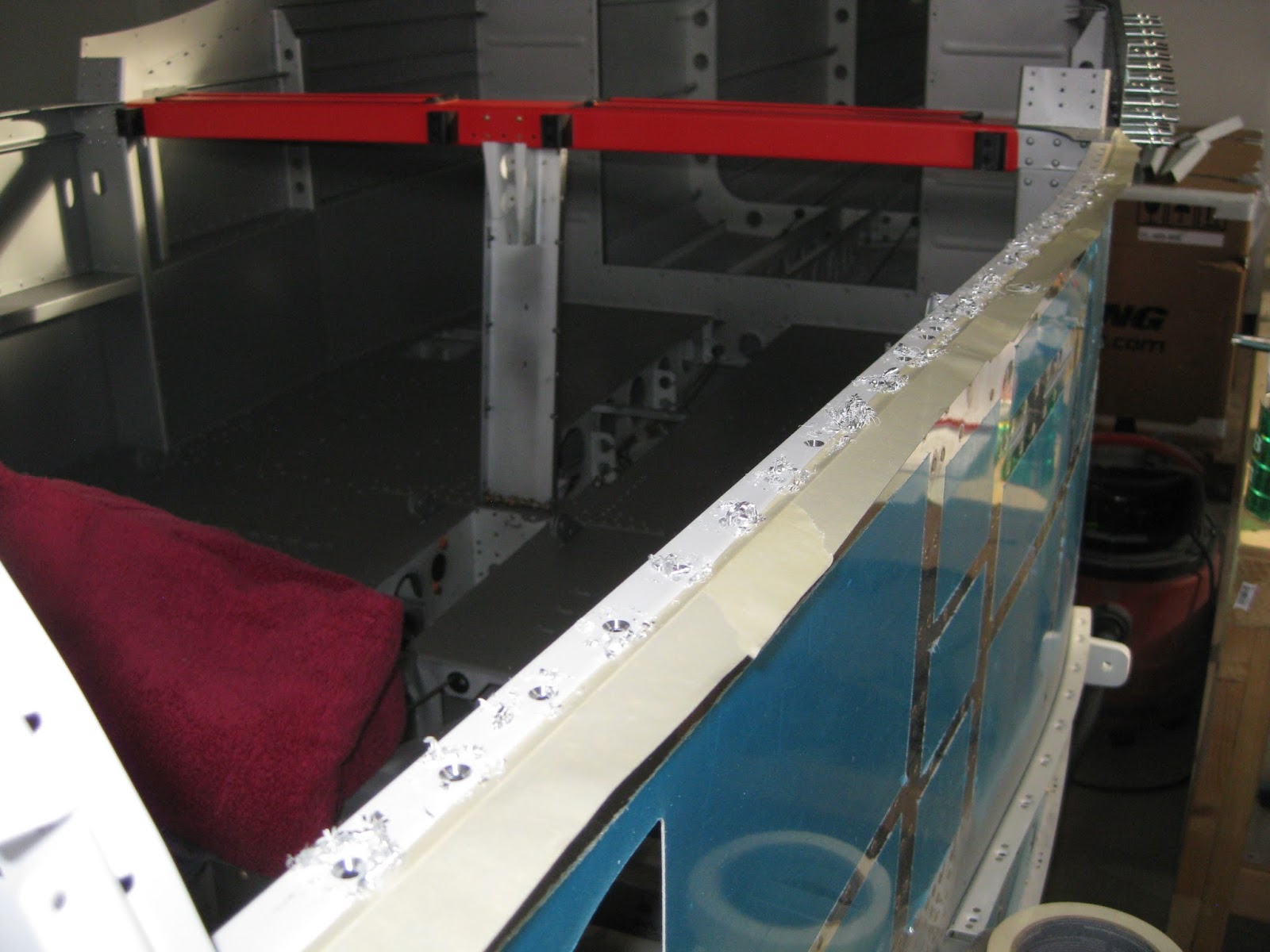
The frames are then fully cleco'd with all of their requisite parts, so that match drilling can commence. Here, every other cleco has been removed to support the match drilling process, later replaced with copper clecos (as an aside, I actually had to buy more copper clecos to complete this step).

The F-01431D window shims need to be countersunk for CS4-4 rivets (remember to use your 120° countersink). Those shims aren't very thick, so without additional support, the holes would be hollowed out by the countersink pilot. Thus, I chose to countersink the shims when they were cleco'd on the roll over structure. Also, prideful rivets aren't desirable here, as the rear window rests on the shims.

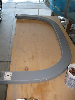
The parts are then uncleco'd, deburred and taken out to pasture, where they are cleaned, acid etched, scuffed, cleaned again, then primed (I opted to use Napa 7220 rather than mix up a batch of two part epoxy primer for such a small job, though a few parts were already primed previously and are thus white rather than gray). The parts are riveted together.
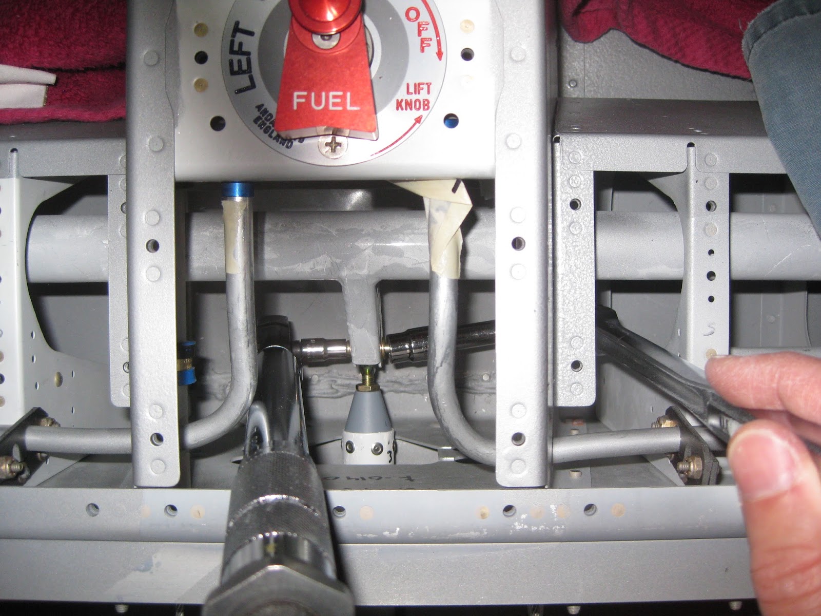
Some match drilling into the roll bar bases...

Not yet knowing what my exterior paint scheme is going to be, and realizing that once the rear window goes on, painting the roll over structure becomes difficult (and impossible for the upper arc underneath the window), I decided to paint it the same color as my interior. I considered painting it black and even red, but decided that using the interior color would give me more options for the later, undefined, exterior paint scheme.
I had painted the F-01432A Roll Bar Brace red when I previously painted some other smaller parts red. I painted the brace impulsively, not really giving much thought to how that would affect the options for the exterior scheme (so I guess I'm going with some red). And, I thought it would create some unobtrusive eye candy if I were to paint the C-01432 Bushing Doubler and C-01433 Bushing Covers in some contrasting colors. So the scheme should look like the below:

Following final riveting, the final product is as below.


The F-1231E Roll Bar Splice Plates are riveted on with the F-01431A-FL/FR Roll Bar Frames temporarily placed on the F-1231D Roll Bar Bases to lock the frames in place (below). I was able to get the forward frames to easily align together with the bases and splice plate. The aft frames, however, required significant prodding to achieve alignment.

The frames are then fully cleco'd with all of their requisite parts, so that match drilling can commence. Here, every other cleco has been removed to support the match drilling process, later replaced with copper clecos (as an aside, I actually had to buy more copper clecos to complete this step).

The F-01431D window shims need to be countersunk for CS4-4 rivets (remember to use your 120° countersink). Those shims aren't very thick, so without additional support, the holes would be hollowed out by the countersink pilot. Thus, I chose to countersink the shims when they were cleco'd on the roll over structure. Also, prideful rivets aren't desirable here, as the rear window rests on the shims.

The parts are then uncleco'd, deburred and taken out to pasture, where they are cleaned, acid etched, scuffed, cleaned again, then primed (I opted to use Napa 7220 rather than mix up a batch of two part epoxy primer for such a small job, though a few parts were already primed previously and are thus white rather than gray). The parts are riveted together.

Some match drilling into the roll bar bases...

Not yet knowing what my exterior paint scheme is going to be, and realizing that once the rear window goes on, painting the roll over structure becomes difficult (and impossible for the upper arc underneath the window), I decided to paint it the same color as my interior. I considered painting it black and even red, but decided that using the interior color would give me more options for the later, undefined, exterior paint scheme.
I had painted the F-01432A Roll Bar Brace red when I previously painted some other smaller parts red. I painted the brace impulsively, not really giving much thought to how that would affect the options for the exterior scheme (so I guess I'm going with some red). And, I thought it would create some unobtrusive eye candy if I were to paint the C-01432 Bushing Doubler and C-01433 Bushing Covers in some contrasting colors. So the scheme should look like the below:

Following final riveting, the final product is as below.