Showing posts with label 40A Tricycle Landing Gear and Engine Mount. Show all posts

07 February 2016

Finish: Tricycle Landing Gear and Engine Mount. Wheels and brake lines on.

This was a satisfyingly quick set of tasks.

The axle toe is first measured using a simple geometrical technique excellently described on page 40A-08.


The wood blocks must first be aligned (left), then the thread is attached and pulled taut (right).  The gap is best measured with the feeler gauge (be sure to keep any tape outside of the gap to be measured as the tape thickness will cause inaccurate measurements).  I found my build had toe-in on both sides:  0.32° on the right and 0.1° on the left.  I obtained Grove's 0.25° shim part 06-00925 (500x5) from Spruce to adjust the right side.  This should leave me with toe-in 0.07° on the right and 0.1° on the left.


Next the wheel bearings needed to be packed.  There's no need to spend more money to buy additional tools.  Youtube abounds with videos demonstrating how to manually do it:  Here is a video that does a fine job.  I didn't take pictures during the process, as I favored packing the bearings rather than my digital camera.

Next, the giant MS21025-24 nut must be torqued so that the U-01430 Nose Fork moves at 26 pounds of force, as illustrated on page 40A-07 (left).  That nut requires a 1.75" jaw wrench or socket.  Though I'm generally not a fan of Harbor Freight products, this cheap socket set fit the bill and worked great (Harbor has an ever-present 20% coupon, which knocks $12 off).  To measure the 26 pounds, I snagged a cheap fishing scale from Amazon (right).


I described in a previous post why I went with the Matco axle for my nosewheel.  The axle is shown on the left and placed in the wheel, on the right.  As another builder explained on his site (about 1/3 down that page) and on VAF, when using the Matco axle, there is no need to drill the Nose Fork for the anti-rotation bolt (it would anyway later interfere with attaching the fairing bracket).  The reason being that the Matco axle allows for the bolt holding the axle to be fully torqued to spec, unlike the Van's axle.


The wheels can then be mounted.


And finally the brake lines can be cut, bent and installed.  The left wheel and right leg are shown below (I may need to rebend the lines when the fairing brackets are installed in Section 46A.  The plans call for "friction tape" to hold them in place.  I had to educate myself on what that was.  I decided to purchase 3M Temflex 1755 Cotton Cloth Friction Tape from Amazon and will install it when it arrives.


So Section 40A is complete once I safety wire the brake caliper bolts.


11 January 2016

Finish: Tricycle Landing Gear and Engine Mount. Gear legs and mount on.

This was a very difficult section for me.  The U-01401 Main Gear Leg as provided doesn't fit through the U-01402 Lower Gear Brace.  I came to understand that some builders beat the leg into place by using a heavy hammer.  However, I believe that approach isn't ideal as it places the parts in tension, which could lead to later failure. 


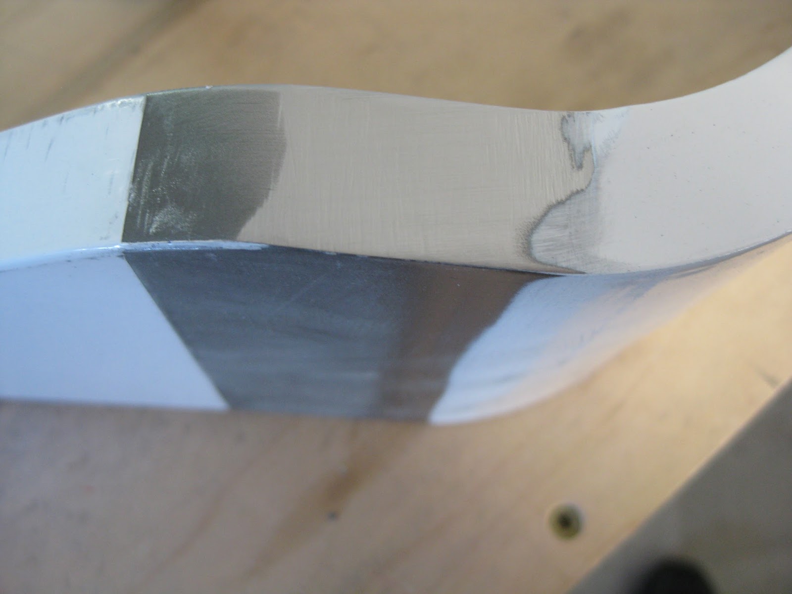
A consultation with Van's elucidated that during the Main Gear Leg's manufacture, the heating and bending processes can cause the edges of the leg to bow outwards, effectively increasing the thickness of the leg (in the fore-aft/longitudinal axis).  Thus, it is acceptable to file down the edges to achieve proper fitment.  The left image shows, after some initial filing, the contact area that was binding the Main Gear Leg and Lower Gear Brace.  A few iterations of 1) gently filing those areas symmetrically on both sides until the marring marks disappear (right), 2) attempting placement of the leg, ad nauseam. and the gear leg will eventually get a tight fit without the use of excessive force or undue rocking.


Additionally, significant powder coating was removed along the gear leg surface that contacts the Lower Gear Brace and the U-01403 Gear Attachment Bar.


The next hurdle was getting the gear leg to fit properly between the Gear Attachment Angle and U-01404 Upper Gear Brace.  On the left side there was a 0.020" gap (as measured by the feeler gauge) prior to torquing the NAS1306-22 bolt.  Van's suggested torquing the bolt to see if the gap closed.  Following torquing, the gap persisted at 0.008".  Van's then recommended to include a 0.016" shim from F-14129A Gear Shim.  It took a lot of effort to place that shim, however afterwards the gap remained at 0.0015" (not a typo) at the top, down to the bolt shaft and was 0 at the bottom.  The right side did not require a shim and had the same gap at the top and also none at the bottom.  I accepted this and continued.  Left gear leg on left and right on right.


The next challenge was placing the U-01403 Gear Attachment Bar.  Originally, I thought this part needed to sandwich the Main Gear Leg against the Lower Gear Brace so that all three parts lie flush against each other, especially the Gear Attachment Bar to the Lower Gear Brace.  However, a consultation with Van's informed me that the Gear Attachment Bar should not be flush against the Lower Gear Brace because if it were, then the Gear Leg may not be properly captured by the Gear Attachment Bar.  Indeed, the gap between the Gear Attachment Bar and Lower Gear Brace is significant following the torquing of the bolts.  In fact, the left gap shown below (from the right aft side) is 0.030".  I could not get the feeler gauge into the space to measure the right gap (from the right fore side).  The left side is similar to the right side shown below.


The engine mount was easily done solo in 30 minutes.  I was even able to torque the lower four bolts, leaving the top two loose to accommodate the later riveting of the F-01471 Forward Top Skin.


The U-01406 Nose Gear Leg went in easily enough, after removal of requisite powder coating.  I still need to verify the tightness of everything then bend the cotter pins down (it's worth noting that Van's Support stated to torque the MS21045-6 bolt, top of Figure 1 on page 40A-06, Step 6, to spec.).  The only thing worthy of mention is that if you're doing this work solo, have something to keep the leg from rotating downwards prior to attaching the gear link assembly parts, otherwise the Nose Gear Leg will fall through the F-14132 Tunnel Angle on your firewall and make life miserable.


So just the placement of two gear legs took me an extremely frustrating 50 hours, 10 of which were with help, whose duration had me wanting to throw in the towel and go buy a flying Lancair with the money I don't have.  With the information I learned through this process, I could have placed them myself in no more than 2 hours.  It would be helpful if the plans were more specific (see my suggested approach below), especially given that the parts are almost assured not to fit on the first attempt.


Here is how I would attach the Main Gear Legs on my next build (this departs from plans slightly):
  • Per plans, attach the Upper Gear Brace.
  • Carefully and slowly slide the Main Gear Leg into position until it binds.  
    • Do not rock the Main Gear Leg or force it into position.
  • Remove the Main Gear Leg and note the marring on its fore and/or aft surfaces where the binding occurred.
  • Gently file down this area until the marring mark is removed.
  • Repeat previous 3 steps until the Main Gear Leg can slide fully upwards into position.
  • Mark where the powder coating needs to be removed so that the area on the Main Gear Leg where it contacts the Lower Gear Brace and Gear Attachment Bars are bare. 
  • Remove the Main Gear Leg and remove the identified powder coating.
  • Attach the Gear Attachment Angle.
  • Slide the Main Gear Leg back in to position.
  • Shim as necessary and torque the bolt through the Main Gear Leg.  
  • Attach and torque down the Gear Attachment Angle.  
And generally:
  • Lubricate all bolts prior to placement being careful not to get lubrication on the threads.
    • If a bolt requires significant force to push through its hole, verify alignment rather than beating the bolt in.
  • Do not spin bolts to torque their nuts.   
    • Crow's foot wrenches are ideal.  I used ratcheting open-end wrenches until the nuts started tightening, then switched to a torque wrench, using a crow's foot when necessary.
    • Adjust torque as required to account for any additional moment arm (it'll probably be near 5 in-lbs reduction for a medium sized wrench, so if you don't torque to max spec, you probably don't need to bother).
After the first landing and for several hours afterwards, I will check the three bolts for each Main Gear Leg to ensure they remain properly torqued.

04 December 2015

Finish: Wheels assembled.

I put together the wheels.  It was a 3 hour affair for me as I had some learning to do.  After scouring my local grocery store for talcum powder and realizing that baby powder is composed of corn starch, I purchased Tire Talc from Spruce (that stuff makes a mess) as part of another bolus of parts I needed.  Update 16-Jan-16: If you look carefully, the main wheel in the left image below has the valve stem aligned with a pink dot (which looks red at night).  I had to disassemble and redo both main wheels to align with their red dots.


I did pay heed to the discussion on VAF about the nosewheel in the kit being the wrong size (Grove NW501.25 vs NW511.25), discovered by another builder who documents his build on his blog, specifically detailing the nosewheel issue on this page.  A terse summary of the issue is that for the wheel provided in the kit, the valve stem will have an extended protrusion, causing it hit to the fork.  The NW511.25 does not have that issue (below, right) and retains the use of the same tire and tube.  Matco allowed me to swap my unused NW501.25 for the NW511.25 for $21.49 plus nearly $20 shipping (though the box came with $3.25 postage due, so shipping was more than $23), putting the cost of the exchange at nearly $55 when the shipping for the old wheel is included.  A reasonable cost, in my opinion.


However, also in that discussion and blog post above is an outline on why one might want the Matco axle over the one provided in the kit by Van's.  In fact, a builder verbosely documented his thoughts on the axle here as it relates to the similarly equipped RV-10.  Summarily, the Van's axle and spacer (below, left) doesn't let you adjust the bearing preload independent of the load imposed by the fork.  This may lead to the parts rotating against the fork, causing undo wear manifesting in shimmy, indicating a wheel that isn't rigidly attached to the fork.  Whilst I'm no expert in this area (well, in any area really), I opted to use the axle and spacer provided by Matco (below, right) for the additional cost of $62.66 and $12.32, respectively.


As shipped, the whole changeover was $116.19 to Matco, plus the $3.25 postage due when delivered, plus $10.06 additional to ship the original nosewheel back to them.  So $129.50.  If one were to delete the parts NW501.25, two of  U-1023, and U-1009 from the finish kit in favor of NW511.25, WHLAXLE24 and WHLA24SPKIT from Matco, I'm sure the total cost of this change would be reduced significantly.

Finally, it's worth pointing out that the nosewheel lacks a grommet for the valve stem whilst the main wheel have the grommet.  I put in an email to Matco inquiring about this curious omission.  Their reply was "There is no grommet for the valve stem hole".