26 May 2013

Wings: Rear spar. Flap and aileron brackets riveted.


Following the priming of the rear spar components, previously, it was time to rivet together the aileron brackets.  Here they are, front and back.  The white/gray ones are due to there being two kinds of primer on them.  White:  EkoPoxy.  Gray:  Napa 7220.  On these brackets, I didn't like how the AN426AD4s were sitting in the countersinks.  They were just barely proud.  So I hit the holes again with the countersink bit to make sure the rivets would be perfectly flush, then spot primed the holes (hence the gray).  


One of the tasks required in assembling the aileron brackets is pressing in a bearing at the apex of the parts.  They suggest pressing the bearing in on a vise with a 7/16" and 9/16" socket on both sides.  It took some finesse, but I finally got the hang of it.  Of course, it just pushed out all the primer in the hole.  Here's a shot looking down on the vise with the sockets lined up on a bearing bracket spacer.  Slowly increasing the vise pressure pushes the bearing in.  Then, I double-checked to make sure the bearing wasn't seized due to warping.  When riveting the apex together, I applied clamping force with the vise to reduce any separation of the three bracket constituents.


Once the rear spars had all their doublers riveted in place, it was time to ream the critical hole.  That encompassed lining up the spar on the drill press and using the level to make sure everyone was orthogonal.  Here's a close-up following the reaming of the left rear spar.


And finally, here are the rear spars, ready to be riveted to the main spar via the ribs.  The yoke on the Main Squeeze couldn't quite reach in there without terrorizing the ribs.  Since I really don't want to bang these rivets with the gun, I'll pick up a longeron yoke to get the extra reach.  So, until I get that part, it's time to take a break from building and go play in the sky with a working airplane!


Wings: Obligatory image down a wing.

In reading the blogs of others, there seems to be a theme in taking an image through the lightening holes down the ribs after they've been installed.  I'm curious about the history of this tradition.  I like it, so below are my offerings as part of the community.  On the left wing, I took images down each of the four lightening hole "paths" as a pair:  One with the flash, one without.

Forward most holes.


Second forward-most holes.


Second aft-most holes.


Aft-most holes.


25 May 2013

Wings: Rear spar. Priming rear spar.

4 hours of prep and priming and all parts for the rear spar are done, including some J-stiffener.


The night before, I was thinking that I should test the spray gun since I last primed the ribs.  I figured something might have gummed up in there despite my having fastidiously cleaned it out after using it the first time.  I didn't get around to doing that.  So after cleaning and etching all the parts, I fired up the gun with some water and all that came out was air.  1 hour later, following a near complete disassembly (and serious consideration of an emergency run to buy a new gun), I determined that the plunger which controls the valve opening/closing the fluid was stuck and wouldn't open.


  Next will be :
  1. Riveting together the new right torque-tube bracket to fix my error from before.
  2. Putting the inboard-most rib on the right spar.
  3. Riveting that torque tube support bracket to that rib.
  4. Riveting the aileron brackets together.
  5. Riveting the various doublers to the spar.  
  6. Ream out the "critical hole" in the forks and doublers.  No mistakes allowed here.
  7. Rivet the rear spar assemblies to the ribs on the main spar.


24 May 2013

Wings: Rear spar. Dimpled and doubler plates fabricated.

Been working on the rear spar.  As part of that, you're required to build the aileron hinge bracket assemblies.  These parts are not straight after having been manufactured, so into the vice they went, sandwiched between pieces of wood, and slowly worked as straight as can be.  The rear spar reinforcement fork and doubler plate are also hopelessly warped.  It takes a lot of time to straighten those out.

The WD-1007D-L/R Outboard Rear Spar Doubler Plates need to have a funny-shaped hole cut into them to fit the aileron pushrods.  A search of the 'net shows that these holes are problematic for many people in that their pushrods rub against these holes.  There's no way to test them until the ailerons are installed.  The plans provide templates to use to make the holes for both wings.  Turns out, they're not properly scaled on the paper, so I rescaled them and printed them out.  Even still, one of the rows of holes doesn't line up.  But all the others do and I checked it against the spar and the pushrod template is in the right place.


I use the center punch to start those holes with a #40 and worked my way up to a 3/8", then sanity took over and I used the unibit to enlarge the holes all the way as shown in the template.  The shaded areas need to be removed via some other means.  My Dremel didn't have any tip that would fit the bill, so I tried to drill a series of holes to file through.  This was after I wised up and used the rear spar itself to trace out the shape of the hole (the paper method was good for the center punch locations).


But there was still too much material.  Off to Home Depot I went to grab a nibbler.  They don't have them in the store.  Amazon Prime to the rescue with $3.99 overnight shipping for a nibbler.  This nifty tool made short work of the aluminum. I used this 1/8" aluminum oxide grinding stone on my Dremel to round it out.  It's basically a really bad cutting stone.  It melts the aluminum very slowly, making it easy work, except when you want to remove a lot of material.  Then you have to be mindful of the heat generated.  Next it was just smoothing all that down to look and feel pretty with sandpaper and the miraculous 
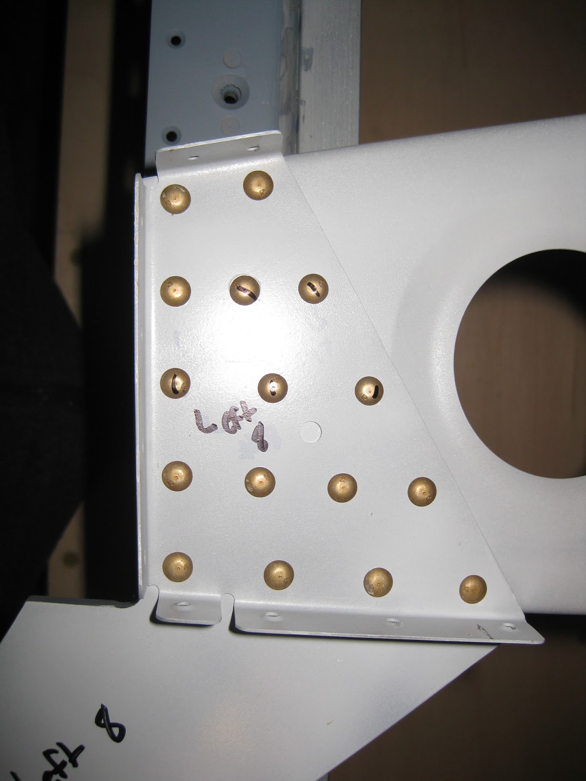
finishing sander.  Below is the right side.  The left side isn't as good.  The nibbler doesn't fit at the top coming from the unmarked side (due to the flange), so I clipped just a bit too much off on one bite using the nibbler from the other side.  Won't be a problem.


On the rear spar, at the aileron attach points, there are doubler plates.  Not sure why (perhaps due to material thickness?), but the top flange of the rear spar that corresponds to the length of the doubler plates gets countersunk rather than dimpled.  So, off I went to countersink on the left wing's doubler first, utterly terrified since screwing up this piece would be costly.  I set the microstop using a piece of scrap angle, then went to the rear spar.  The bit chattered in the hole and it got elongated.  I did it to the next two holes too, though not as bad (all other holes, around 30-some total, are fine since I slowed down the drill speed).  I'll either need to 1) enlarge these corresponding skin holes to a #30 and use the Rivet of Shame or "oops" rivet (NAS1097AD4, shank of a AD4 but head of an AD3) and furthermore, pre-compress the rivet to make sure it fills that weird hole reasonably, 2) just set it up for a AN426AD4 all the way through or 3) replace the part.  Oops indeed.


Every part in Section 15 needs to be deburred:  Holes and edges. Turns out my hand-held screwdriver is a major hand-saver for this.  And I managed to find a way to run the spars across the Scotch-Brite wheel.  Time saver!

Both flanges in the rear spars have to be dimpled, where they weren't countersunk.  I used the DRDT-2 on the bottom flange since that flange is orthogonal to the web.  But the top flange is acute to the web, so using the DRDT-2 would distort the flange.  Instead, I used the Main Squeeze for those, ensuring that I aligned it properly to the flange angle before each press.  A piece of electrical tape on the backside of the Main Squeeze prevented it from gauging the web.


I also went ahead and deburred and dimpled the top J-stiffener (it's the first thing prepped in Section 13 and is installed in 16) so I can prime it with these parts.  I thought it was a good idea since the wing skins will be big and awkward during their prep without the J-stiffener floating around in the way too.

Tomorrow is etching and priming.  Then everything gets attached.

16 May 2013

Shop: New drill press.

The "Craftsman 10 Bench Drill Press with Laser Trac reg 21900" is gone.  Darn thing just wobbled no matter what.  It cut elliptical holes, in fact.  I picked up the Skil 3320-02 from Amazon. 


Cheaper, better built and drills true.  Sears wouldn't give me my money back on the Craftsman because it was past 90 days since I bought it (sat on it too long), but they kindly gave me an in-store gift card.  I'm sure I can find a way to burn that there.

11 May 2013

Wings: Ribs. Riveted to spar.

The ribs have been riveted to the wings.  Except for the outboard ribs (as per plans) and the most inboard on the right side (W-1010-R) since I need to redo the torque tube support bracket due to...operator error.  This was a full 7.5 hour affair with the help of my friend, a successful RV-9A builder.  We drilled out and replaced about 6 rivets.  That's not too bad.


08 May 2013

Wings: Flaps. Brackets riveted to ribs.

Section 15 is done!  Picked up an inexpensive torque wrench from Harbor Freight to complete the last page in Section 13, page 13-05 (bolting the aileron bellcrank brackets).  I generally avoid Harbor as a source of tools since it seems like many things there are sub-par, but the feedback on the 'net was quite positive about this wrench.

Snap bushings are installed on the ribs.  Turns out I put in an extra 1/2" hole in rib #9 (from inboard) on the right side.  No big deal.

Each of the 4 flap brackets and their doublers are riveted to the associated ribs (#3 and #8).  I was able to squeeze five of them (the ones with the lines on their heads).  The rest had to be banged out with the 2x gun.  I used 90 psi on these -4 rivets.

This is the #8 rib on the left side.  You can see the Stewart System's EkoPoxy/EkoPrime.  It appears to hold up well.


07 May 2013

Wings: Ribs. Prime rib.

2 hours later, all ribs are cleaned and etched, including all the smaller parts like brackets and so forth.  I decided to use Stewart Systems' offerings, including EkoClean, EkoEtch and EkoPoxy/EkoPrime.  Getting these guys to dry is a challenge, so here they sit, under the ceiling fan (pardon the wing tips, that's the best place to store them until they're needed).


Here's the priming extravaganza.  I practiced with the spray gun using water.  I tried to calibrate the air pressure, air volume and fluid volume.  I knew this was going to be a learning experience.  I wasn't sure how much to spray on the parts.  The instructions call for 3 mil.  How to measure that?  I don't know.  Thus, I sprayed enough so it appears that the metal is covered.  Sometimes I sprayed too much.  Sometimes too little.  The latter was easy to fix.  If the former is too bad, I can sand it down.  EkoPoxy dries slowly, so you can't turn over parts to prime the other side.  That was a challenge.  Overall, it took 2.5 hours to prime the ribs and the other parts from Sections 11 and 12.


It's probably fair to say that each rib will have received at least 1.5 hours of work associated with it prior to riveting on the spar.  28 ribs=42 hours.

05 May 2013

Wings: Ribs. Final drilled to spar.

Flap-brackets are final-drilled and their associated ribs have been match-drilled.  The torque tube support assemblies are ready.  Conduit holes are drilled in the ribs.  Most holes needed to be enlarged, however some holes needed to be created.  Using a punch is not the way to go as it deforms the web.  So I used a smaller bit, about 1/32", to create the hole, enlarged it with a 1/8" then used the unibit for final-sizing.  Some of the conduit holes are 1/2" so using the hand deburring tool was a non issue on these larger holes.  For the smaller holes, the 400 grit sandpaper worked fine.

Next was removing the bolts from the web of the spar.  Some of these came out easy, others were extremely challenging.  Almost as though the hole they were sitting it wasn't big enough.  With the bolts removed, the ribs get cleco'd onto the spar so that 1) the #30 holes in the spar web and rib forward flange can be final-drilled, 2) the forward flanges of the ribs can have the bolt holes match-drilled with a #12 and 3) final-size drill the #40 holes on the rib tabs (which I had done previously since I looked ahead at the plans).  Using a #12 bit to start a hole on the forward flanges is not a good idea.  So I used a #30 bit to start the hole and final-sized it with the #12.

Left spar and right spar.

    
Cleco'ing in the ribs on the right spar.


Next comes prep for priming.