Showing posts with label Capacitive Fuel Probes. Show all posts

14 June 2014

Wings: Fuel tanks redo. Capacitive plates installed. Tanks passed water test.

Because I'm redoing my fuel tanks, I'm really only posting progress reports rather than additional details.  See here for why I'm redoing my tanks.  Technique details on the original fuel tanks are found in their associated posts.

Capacitive plates installed (see here for how these were fabricated on the original tanks).  I feel like I did a much better job than on my first tanks.  Right tanks on top.  Left tanks on bottom.  Just need to tack seal a couple of places along the wires before I call this "done".


Tanks passed the water leak test, save for some leakage around the float sender's hex screws for both tanks, which is an easy fix.  I took the same approach as I did for the first tanks, just no food coloring or toilet paper.

17 September 2013

Wings: Fuel tanks. Left tank capacitance probes and baffle install.

I decided to redo my fuel tanks.  See here for why.  The entries specific to the redone tanks are here.

Capacitive probes on left tank are installed.  I had to replace a screw from last week since it got stripped going into the nutplate.  Thankfully the nutplate wasn't damaged.  The work for the left tank was identical to the right tank, so I won't go into as much detail here.

I put the masking tape just over the skin's baffle rivet holes this time.  Turns out it wasn't as useful as I had anticipated:  When the tape is removed, it just takes the sealant bead with it since the bead just fell aft onto the tape.  Here is the sealant on the skin ready for baffle install.  You can see the capacitive probe wire in the image.


As with the right tank I put a very thin layer of sealant on the baffle flanges (shown below) and aft rib flanges.


Here is an image looking aft through the filler flange to see the sealant along the baffle-skin joint.


And here are the "shop heads" of the AD-42H blind rivets along the rib flanges as seen through the filler flange.


I had to remove a AN470AD4-4 rivet I put on the outboard attach zee (it needs a -5).  With all the wet sealant, I realized a "chip catcher" was necessary.


And here is the left tank, inverted for curing.


I also countersunk for and placed the final baffle rivets on the right tank.  After it cures, it will be test time.  Once the left cures I will go through the same process.

11 September 2013

Wings: Fuel tanks. Right tank capacitance probes and baffle install.

I decided to redo my fuel tanks.  See here for why.  The entries specific to the redone tanks are here.

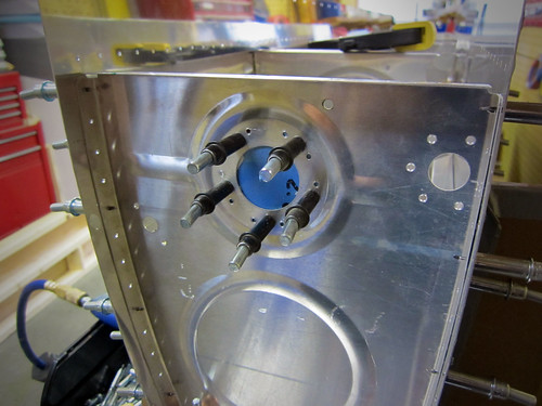
For the installation of the capacitance probes, the RV-9 plans require you to cut a notch out of the vent line bushings to fit the wires.  Well, I had already installed the vent line, so that wasn't a viable option.  I didn't like the Van's method anyway since the wire could still fray up against the ribs with the notch removed.  Turns out there is a 7/16" hole at the top-aft of each rib which must serve the purpose of helping the fuel move around a bit or perhaps a tooling hole.  Since it's at the top of the tank, it wouldn't be a big deal to occlude it a skosh (effectively reducing its diameter) if I slipped in a bushing to carry the probe wires through.  So that's what I did, winding the wires around the vent line to help anchor them.


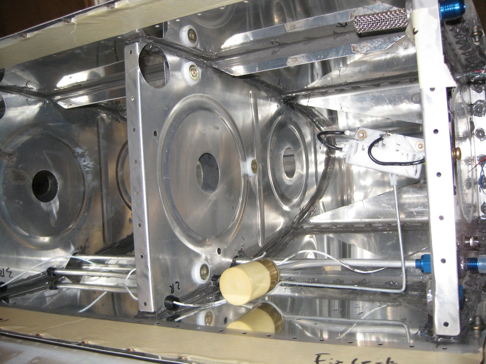
Capacitive probe on rib 6, inboard and outboard sides, prior to final sealing and tacking of wires.


Capacitive probe on rib 2, inboard and outboard sides, prior to final sealing and tacking of wires.  Note the fuel float.  I will be using both means of fuel measuring (one for EFIS, one for steam).  Also the low fuel level optical sensor is visible.

For installing the baffle, since it needs to be sealed on the inside, the plans call for the following sealant methodology.


After dropping in the baffle, using a more liberal interpretation of the above, here's what the sealant looked like prior to the baffle install.  This was done with two stripes of sealant using the manual syringe gun.  For the left tank, I'll integrate some of Mouser's approach to mine.


And here's what the sealant looked like against the baffle inside the tank (the below image was taken through the fuel filler hole).  The sealant bead at the top is the baffle-skin joint (i.e., ignore the arrows).  I also put a very thin layer of sealant (thin enough to prevent skin pillowing) on the inside of the baffle flanges.


And here are the baffle and attach zees cleco'd.  I decided to sand down the primer I originally put on the tank attach zees' flanges so the sealant could get a better grasp of the parts.  May not matter, but surely won't hurt, especially considering how ridiculously tenacious that EkoPoxy/EkoPrime is!


Where the baffle webbing attaches to the ribs, all of the rivets are AH-41/2H blind, except the out- and inboard ones which are bucked AN470AD4.  The latter are very easy to buck solo, just be careful not to let the rivets work-harden prior to getting a good shop head.  Also, there is one AN470AD4-5 rivet on that outboard side that requires a deliberate approach since there is a AN470AD6-5 filling a tooling hole impeding good bucking bar access.

The tank will sit inverted for a week or so to promote better sealing against the baffle.  Probably won't make a difference, but it surely won't hurt.  Every rib and baffle rivet head (shop and factory) and all mating surfaces were slathered with sealant, including a fillet at all joints.


After a full cure, the last baffle rivets will be installed following skin countersinking.  Then it will be 1) final leak testing of left and right tanks, 2) priming of the baffle and outside rib faces then 3) hanging of the left and right tanks.

25 July 2013

Wings: Fuel tanks. Prepping for sealant, capacitive probes fabricated and locking caps.

I decided to redo my fuel tanks.  See here for why.  The entries specific to the redone tanks are here.

Here are the tank stiffeners, J-stiffener and fuel cap flanges placed in the skins.  I'm tracing around these parts so I know to what extent I should scuff the interior of the skin for sealing.  I'll do the same for the ribs separately.  Since the interior of the tank skin should not be primed, I want to preserve as much of the alodine layer as possible.


Using my new nut plate jig for the capacitive probes I fabricated.


Match drilling the VA-141 Flange, Finger Strainer to the T-1003B-R Tank Inboard Rib - Aft.


Below is the Tank Inboard Rib - Aft showing the location of the optical fuel level sensor I'll be using as a redundant low fuel warner.  I placed it about 1.75" from the bottom of the tank at that location.  A quick, back-of-napkin, entirely inaccurate calculation suggests this will correspond to a bit more than 5 gallons, which ain't much (Update 10-May-18:  It ended up being about 1 gallon as I didn't consider dihedral).  If the warner goes off, it's either time to switch tanks to a hopefully fuller one and/or find a place to put down of my own choosing.

The T-1010 Anti-Rotation Plate is visible on the left.  Also, there is an additional hole at the top which is for the BNC connector that will be used to connect to the capacitive probes.  I've decided to use both the capacitive probes and the floats as redundant fuel level indicators.  This is for two reasons 1) in case one fails and 2) in case my capacitive probes end up being non-functional or not satisfactorily accurate.


And locking caps which fit the stock flanges (I verified this with Robin at Newton SPRL prior to purchasing).  Left image:  Locking cap with universal flange on left.  Right image:  Caps swapped.  I will be using the setup on the right.  And I guess I'll have surplus caps and flanges.


And why not get a "Remove Before Flight" keychain for the associated keys?

19 July 2013

Wings: Fuel tanks. Capacitive fuel probes.

I decided to redo my fuel tanks.  See here for why.  The entries specific to the redone tanks are here.

Here in the 21st century, in addition to using floats (for steam gauges), I also want to go with capacitive (for the EFIS).  Turns out for the latter there is no such option for the -14 (though there is for other models).  Since the wing of the -14 is essentially that of a -10, there is quite a bit of precedence for fabricating the probes for the wing.  Here are four examples: Brian's RV-10, hanger52Mouser's RV-10 and of course the amazing Ed (pages 1, 2 and 3).  In fact, Ed's fantastic site includes essentially a stencil for the plates.

I printed his out after scaling it properly, precisely cut the paper with scissors and lined up the shape on my tank ribs.  Sure enough, it's a perfect fit.  So I bought the capacitive kit from Van's for the -9 so I can get all the parts then planned to fabricate my own plates using Ed's stencil (since I naturally won't be using -9 plates as they aren't the right size).

I purchased an 18"x16" section of AS3-020 from Van's and cut it down to four pieces 9"x8" each.  I drilled holes on the perimeter and where the mounting nutplates would be then attached clecos to hold each piece together in a stack.  Then, I taped the properly scaled stencil to the stack.  Running it carefully through the band saw, I got the following ("reassembled" to show the original setup):


Then after filing things down a bit (still needs more smoothing of the edges), I ended up with a stack of four nice capacitive probes.


I also got a nutplate jig so I can properly place the mounting nutplates on the probes.  I still need to drill out holes for the wires and fabricate some covers for the stock fuel level sender holes in the ribs (covers the holes for the float apparatus).  See Mouser's picture for reference.

See here for installation on my original & replacement tanks.