
These have been added to my airframe (scroll to the end of this post to see all images of the tips on the aircraft). Read on.

When Aveo Engineering released the original "ZipTips" a few years ago, I thought they were pretty neat and had I not already installed their Hercules 30 landing lights into my wings, I probably would have gone with the ZipTips.
Those Hercules 30 lights have been doing an awesome job at night and during the day. I remain quite pleased with them.


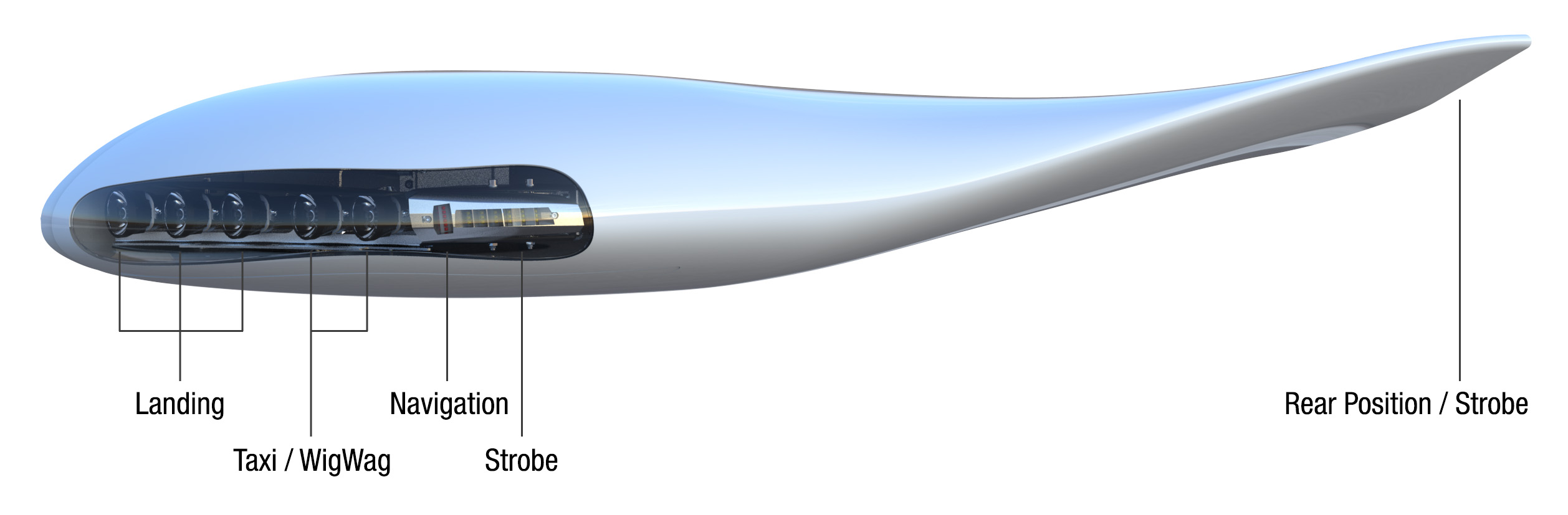
However, when I went to OSH 2021, I stopped by the Aveo booth and really liked the look of their updated "ZipTips Premiere 2" model. Not so much that the lights are in the tips, but 1) there is a rear position/strobe light and 2) that the aesthetic of the upswept tips is very appealing to me.

I emailed Van's for the engineering team's thoughts on any impact the upswept tips would have on the wing structure. Tech Support's response: "I am sure there will be no negative impact of these wingtips on the wing. The wing structure is very strong. Vans [sic] is not really in a position to give any engineering input on this kind of third party product."
Despite no solid guidance from Vans' engineers, I decided go for it. The ZipTips are not cheap: Shipped to me they were $3.74k with an included "free" PosiStrobe JP tail light. The tail light would be useful to replace my SunTail so it cooperates with the strobing of these new Aveo lights. The tips arrived in perfect condition. The lights come installed into the tips with the access panels already cutout.


Turns out Aveo provides a Fiberglas tip rib (though they appeared to have swapped the "left/right" labels). And I included an image of the seam sealing the top and bottom halves. Vans' uses a much wider, though thinner piece of cloth. Aveo uses a much narrower though much thicker setup.


As a comparison to the kit's stock tips from Van's, you can see Aveo's have a wider profile. And the aft upsweep is visible. My original right wing tip, with the VOR antenna, weighed 6 pounds (that tip had an additional inboard layup to reduce cracking). My right ZipTip, as installed weighed 8.75 pounds (includes harnesses).


Just like I did with the original tips back on 1-Dec-13, I rough-cut the ZipTips' flanges: I used 1/2" wide electrical tape as my template. Then went to town with my Dremel.


After filing and sanding the edges straight, the tips were now ready to take to the aircraft and fit.

Since I'd be replacing my original kit's already in-place wing tips, I would need to match drill the new ZipTips with the wing skin holes already drilled to final size and dimpled. Turns out carpenters have a tool for this, sometimes called a "hinge bit". These self-centering bits have an undersized bit encased in a frame that centers into the countersink.

I needed to strap the wing tips into place and match drill the holes, like originally done back in 2013 on the original wing tips.


Then upsize those holes to #27 for #6 screws and use my #6 nutplate jig to setup nutplate holes. Then install the nutplates. Just like I did on 3-Dec-13.


Of note, on both tips, the fore-most nutplates required digging in to the epoxy so that they sat flat against the flange.

I needed to setup the access panels with nutplates.


Then it was on to installing my Archer VOR antenna, similar to how was done in my original tips back in May-17. The antenna has to sit further aft in the ZipTips because the lights are supported by brackets that are contained in a Fiberglass box. And it turns out that the hole spacing along the outboard edge of the wing skin is not consistent. So the antenna needs to be match-drilled again. One could replace the metal piece that needs to be match drilled with a new one, but a few extra holes won't appreciably affect reception performance (I didn't take a picture of the antenna before I made the harnesses).

For the wiring, I had to make sure my airframe could handle the spec'd current demands. To run both the Herc 30 lights and the ZipTips would require ensuring the gauge is proper for the path. On the "high" setting, the Herc 30 lights draw 4.2 A for the taxi segment and 6.3 A for the landing segment only, per light. The ZipTips draw 2.5 A for the taxi and 4 A for the landing (there is no hi/low setting). Thus with one set of Hercs and ZipTips powered on together, the max would be 6.7 A for taxi and 17 for taxi+landing (with wig-wag on, the max would be 17-4.2=12.8)
My Otto K2 panel switch can handle only 16 amps. However the design of circuit board for that switch that I made back on 2-Nov-16 was fortuitous since I designed it in such a way that when the taxi+landing position was selected, the current for the taxi light is not carried through the K2 panel switch, rather that current is carried through my circuit board. Thus, I will not exceed the spec of the K2 panel switch (since only 10.3 of current would go through the switch and the remaining 6.7 would go through the circuit - per light)!
The four wires from the panel to the landing lights are separate 14-gauge runs to the landing and taxi lights. So those wires would be able to handle feeding both sets of lights (Herc 30 and ZipTips). The fuse block I designed back on 27-Dec-16 has 18 gauge wire going to the panel. I had to pull those wires from the panel and replace them with 14-gauge. It took only 2 hours on my back upside down under the panel to do that.
Then, I needed to assemble a wiring harness at the outboard part of the wings to allow both the Herc 30 and ZipTips to be connected. I can't select one light set or the other. E.g., when I turn on the taxi lights, both the ZipTips and Herc 30s come on. But I can select hi/lo for the Herc 30 lights. However, should I later prefer to be able to select one setup of lights over the other, it would be trivial for me to run a thin 24-gauge wire out to my harness which would control an-easy-to-design circuit board that would plug in to that new harness.
The ZipTips come with an extremely short pigtail, which is unfortunate. If it was 2 feet long, then I wouldn't need to make an intermediate harness (Update 10-Sep-21: this feedback was provided to Aveo - going forward the pigtail will come with 2' of wire). Anyway, I laid out the parts to make the harness for the lights at the front of the tip.

Here are the harnesses from the Aveo lights (left) and to both my landings lights (right). The idea behind the harnesses on the right image is I can plug in to the wing wiring and then plug in to both my Hercules 30 lights and the ZipTips. I didn't have 16-gauge wire on hand so I could only use 14-guage wire for the power and ground wires. Since it's impossible to shove two 14-gauge wires into the Molex connector (see here for part used), I spliced into the wires by pulling back some insulation, soldering in the Y connection and covering the exposed areas with solder sleeves. It turned out to be really clean. The harness in the left image has a plug for the ZipTips' landing lights and one for its front nav/strobe.


Since the ZipTips have nav/strobe lights in the front and back, I needed to have a little splitter come off the back nav/strobe that would then plug in to my harness for the front lights. Here's how that looks on the left and right tips. I spliced in the wires using solder sleeves since I ran out of male Molex pins.


Since all four of lights are Aveo, I figured the master-slave select line for the wigwag function would work the same for both sets of lights. Turns out it's not: For the Hercules 30, when you ground that line, the associated light is defined as slave. For the ZipTips, it's opposite. So not wanting the left Herc 30 on when the right ZipTip is on and vice-versa, that needed to be addressed which adds a minimal complication: My left Hercules 30 light now has the line grounded whereas the right ZipTip has the line grounded. That required some shifting of wires around and soldering in new jumpers since my original installation had the right Hercules 30 with that select line grounded. Not a big deal, but it did eat an hour to track down the confusion and shift the wiring.
Next it was time to properly locate and install the wing tip ribs, though unlike how I did back on 29-Jun-14, since the ZipTips come with glass ribs, I chose to bond them in rather than rivet them. Holes for the clecos were ultimately filled with Easy Sand.

The wing tips sit 3/16" below the ailerons when the latter are in a neutral position. I think this might be related to the ZipTips being developed for the RV-10, which does not have the flaps and ailerons sitting in a -3 degree reflex position. Because the ZipTips are very rigid, especially at the trailing edge, and that there's a light back there, adjusting the location of the trailing edges is not feasible.


I found the following current draws when the Hercules 30 and ZipTips are all on:
| Wigwag | ||||
| Low | High | Low | High | |
| Taxi | 8 | 12 | 4 | 6 |
| Taxi+Landing | 21 | 34 | 16 | 26 |
The nav/position lights of the ZipTips and PosiStrobe JP tail light represent
an increase in current draw over my original AeroLED's NS90 wing tip and SunTail lights
of 2.08 A and average current increase for the strobes of 2.5 A.
Here's how the plane looks with the new ZipTips. There were no perceptible changes in flight characteristics that I could discern.


Some nighttime shots: The bottom image was captured when the strobes pulsed. It's neat to see the rear position lights. In the top image, the giant bug splatter on the canopy attests to the adequacy of the illumination.


Here's are comparison image from my first night flight back in May of 2018 before the ZipTips were installed It might help show the difference in ground illumination with just the in-wing Hercules lights.

