18 November 2016

FWF: Engine installation.

Time to put the engine on.


I purchased a cheap Harbor Freight engine crane. This is just a welded box steel frame with a hydraulic press.  So I was okay with buying it from Harbor Freight.  The total was $139.61 after a sale and coupon (everything there has a coupon and is on sale - it's how they work).  Assembly was quick (left) and I just had to test it (right).


A series of pictures showing the unboxing of the engine.  The engine was delivered previously.


The crane's legs could not be slid underneath the engine easily due to the latter resting on a pallet, so we used a 500 lb ratchet strap to slowly lift the engine out of its box at an angle.


Removal of the bag revealed a serious amount of desiccant.


The engine was then free to just chill out and hang.


Various fittings and the prop governor needed to be attached whilst the engine was strung up.


It's worth pointing out that the PT-030x1/4 tubing used to fabricate the Fuel Overflow Tube on page 43-05, Step 3 (shown on right), does not require a brass insert (as illustrated on 05-29, Figure 1, shown on left) like the smaller I.D. PT-062x1/4 brake lines.  I confirmed this with Van's:  "This assembly does not require a brass insert like what is needed for the brake lines."  I suspect this may be due to the fluid exiting this tube not being under pressure, however I am not certain.


The Lord mounts are set on the FF-01400 Dyna-1 Tri-Gear Engine Mount.  The durometers are placed differently between the upper and lower engine mount cups.  They are oriented such that the weight of the engine puts the hard durometers in compression in positive G.


And finally the engine was lowered into place.  However it was not a drop-in fit.  It took some finagling.  We also found that a third set of hands was useful.  Especially if those hands are small so that the castellated nuts could be manipulated in the confined spaces they reside.  We found that all bolts needed one additional washer to avoid bottoming out the threads.


Engine mounted.


Just for fun, here are the positions of the airframe before (top) and after (bottom) the engine was mounted.  The weight of the engine and its contribution to the CG are apparent.


Update 14-Jan-17:    Do not neglect to remove the expansion plug from the engine prior to mounting if you're using a c/s prop!

Avionics: Antennas mounted.

You can read about the antennas I'm using for my aircraft.

Per the EAA Hints for Homebuilders, I used DAP Alex Plus latex caulking to seal the antennas to the airframe.  It is a "siliconized latex" so it's paintable.  Here is an example of the bead of caulking placed along the perimeter of an antenna prior to bolting it on.  It dries clear and can be peeled away from unprepped surfaces.


This image shows the two comm antennas and one UAT 978 MHz antenna for the SkyRadar DX ADS-B in.


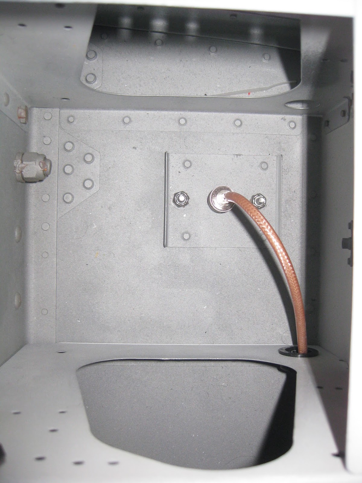
Here is the underside of the GA-35 GPS/WAAS antenna for the GTN-650 GPS/Nav/Comm.  The left image shows the routing of the coax.  I chose not to rivet in the doubler plate I constructed (center).  The side facing the top skin is not primed and primer was removed on the skin around the bolt holes to ensure a good ground connection.  More information on how I mounted this antenna can be found here.


Coax leading to the right and left comm antennas (top) as well as the SkyRadar DX UAT and GTX-330 ES 1090 MHz transponder antenna (bottom).  I plan to fabricate and add a doubler to the UAT antenna.  Although it's close to a rib, that skin is 0.025" and the blade can create significant torquing when slipping/skidding.


The GTX-330 ES 1090 MHz antenna.


The 1090 MHz ADS-B in antenna for the SkyRadar DX has not yet been installed.  I'm still deciding on where to place that antenna.  And the same for the Comant CI-158C-2 VOR/LOC/GS antenna for the GTN 650.

17 November 2016

Empennage: Empennage fairings.

These steps had to wait two years until I had the space to complete them.  The attachment of the empennage is found here.

My friend completed the horizontal stabilizer fairings.  He chose to recess the aft faces since he had issues with the ones on his RV-9A contacting the elevator counterbalance skin.


If I later find that I prefer it flush, I can change it.  Van's demonstrator, N214VA, has them flush, as shown on an image from when I visited Van's on 7-Aug-14.


The rudder fairing is easily attached and match drilled.


The R-00911B Rudder Fairing Doubler (for the tail strobe) is placed, then match drilled (left).  The cutout for the light is then created (center and right).  You can see that the fairing biases to the left (free trim tab?) so I'll need to file it down on the left side and add some material on the right.


The F-01496 Empennage Fairing is attached (left) and blind drilled (right).


The nutplate holes are created in the inboard edges of the horizontal stabilizer and bottom of the vertical stabilizer.


And now I could step back and see the full tail.  Following admiration, then subsequent vocalization of airplane noises, the tail was removed and will be stored until the aircraft is moved to a hangar.  Because the horizontal stabilizer is wider than the car lanes between my house and the airport, it's foolish to transport the aircraft with the tail attached.


Though the vertical stabilizer fairing is visible and complete, I've not yet attached it.  I am still deciding on where to place my Comant CI-158C-2 VOR/LOC/GS antenna for the GTN 650.  I may perch the antenna atop the vertical stab.  Update 18-May-17:  I opted not to use the Comant "cat whiskers" antenna as it proved difficult to install properly.  I ultimately went with an Archer VOR antenna.

Empennage: Empennage attach.

This section had to wait 2 years until I had the space to complete it.  To start, I had to place 165 pounds from my weight set on the engine mount to keep the airframe from tipping back.  Even with that much weight up front, it only took about 20 pounds more on the tail, with everything mounted (stabs, rudder, fairings, etc.), to tip it.


Below is the only image I obtained of the horizontal stabilizer after match drilling it to the F-01411C Horizontal Stab Attach Bars.  It's important to keep the drill bit perpendicular to the parts and not let it chatter or wobble.  These holes need to provide a snug fit for the AN4 bolts.


My friend, who was helping me this week, and I decided to mount and match drill the elevators when the horizontal stab was on the aircraft, contrary to plans.  We felt that it would provide us more space to work with and help align things better.


It was found that the rolled leading edges were contacting both the HS-00903-1 Rear Spar and the HS-912 Hinge Brackets.  My friend spent some quality time massaging the edges into a shape to prevent this.  Recall, I was not pleased with how my rolled leading edges came out back in August 2014 when I rolled them and finally when they were riveted after being "re-rolled" by my friend in January 2016.


Next, the elevators were clamped into an in-trail position.

  
Following the plans with the "E drill bushing" (that bushing needed to be "turned down" on a drill press with sandpaper prior to getting a good fit into the bearing), I could match drill the left horn first (left).  Layering pieces of 0.020" aluminum strips provided for a good spacer.  The right side could then be match drilled in the same way.  Then both holes were upsized with a unibit to accommodate the AN4 bolt (right).  The washers necessary to prevent binding of the bearing are also visible.


My aft-most elevator horn was the right side.  So the hole was marked on that side first to accommodate the elevator pushrod (top left) then it was drilled to size (top right).  A spacer was fabricated, with a perpendicular hole pre-drilled, that was clamped in place to match drill the left horn (bottom left).  The spacer and its hole were important to ensure a perpendicular hole.  The horns could then be attached to the pushrod (bottom right).


Read Van's RV-14 Control Deflections Letter before adjusting control surface stops.  The horns contacted the F-01412C Deck Angle (which serves as the control surface stop in the "up" direction) prior to achieving the required full up deflection.  Quite a bit of it had to be filed away to accommodate the required travel.  I confirmed with Van's that this was acceptable:  "Your work as shown in your picture is perfectly acceptable. This angle is intended to be filed away to allow the appropriate elevator deflection."  Two other builders I contacted did something similar.


My elevator horns contact the Deck Angle simultaneously with the control stick stops in the upwards position.  In the downwards position, the control stick stops engage just prior to the control surface stop (the latter being the F-01411E Deck Doubler).  I have 29 degrees up and 24 degrees down elevator travel.  Were I do build another RV-14A (ha!), I would forgo the hours I put in filing down the control stops on page 36-13 until this step is reached.

I took the occasion of the elevators being attached to test the wiring of my pitch trim. It worked.

The vertical stab is then placed (left) and finally the rudder (right).


Rudder deflection is checked, left and right.  I am at 9/16" on both sides which is 3/16" short of the 3/4" spec.  This means I need to add offset tabs to achieve spec.


14 November 2016

Empennage: Aft empennage. Match drilling vertical stabilizer.

The last step remaining for me to complete in Section 10 was the match drilling of the vertical stabilizer to the aft bulkhead.  I waited until I was ready to complete Section 11 to do this step, meaning it was delayed by 2 years.  I just needed more space.

Per the plans, it is critical to drill these holes perpendicular to the surface.  A friend of mine created for me a UHMW piece to aid in that process.  It keeps the bit trajectory true.  A well cut piece of wood with a hole drilled on a press would achieve the same result.


Once the holes are drilled, the stab can stand proud to negotiate the slipstream.


The above image also shows that the airframe has been moved to the other side of the garage.  This gives space to fully mount the tail to complete Sections 11 and 12 as well as mounting the engine and prop.