16 April 2017

Interior: Koger sunshade installed.

Installed the Koger Sunshade (model TU-WIDE).  It really blocks out the non-existent sun in my garage!  

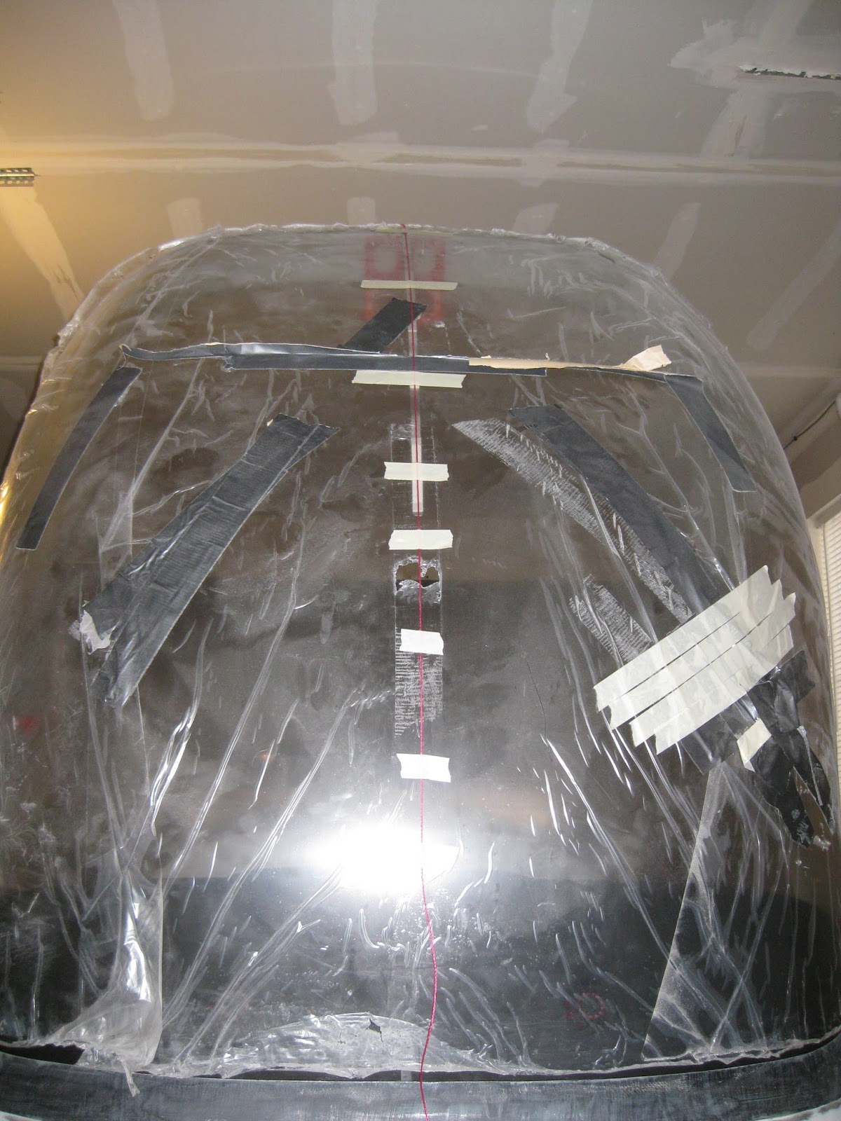
The most important part of the install is to ensure that the track is 1) bent properly to exactly conform to the interior surface profile of the canopy and 2) that it is centered exactly.  The accommodate the second point, I pulled a taut string across the canopy centerline and taped it in place.  Then, once inside, I could affix the track by following the string.


The rail is affixed to the canopy after proper bending.  Then the bows holding the shade are similarly bent to conform to their respective positions.

Top view.


Interior view with canopy raised.


Interior view with canopy down.


11 April 2017

Finish: Miscellenea: Steps powder coated.

Got my steps powder coated.  $40 at a local shop.  I decided on a flaming yellow.  They will definitely stand out, for better or worse.


09 April 2017

Wings: Pitot static. Lines and wiring routed.

Quick set of pics to show how I solved the problem of my Dynon heated pitot/AOA line and wiring routing.  The challenge was that I chose to install the pitot tube in the bay just inboard of the aileron bellcrank.  This meant that the pushrod was in the way.  If I were to do this again, I would put the pitot outboard of the bellcrank

I used two push-to-connect elbow fittings from MettleAir: 1/4" OD to 1/8" NPT, model  MTLF1/4-N01.  This allows connection into the pitot/AOA tubes with minimal additional hardware (unlike my first design back in 2013) as only an AN816-3D nipple was necessary with the elbow fittings.

The two images below are from the same vantage point, with different lighting schemes, looking inboard from the bellcrank inspection hole.


This is looking outboard from the center inspection hole.


The wiring was negotiated to accommodate mounting the controller box on the center inspection cover.


Left pitot tube installed (I have dual pitots in my plane).


Read the entries in my AOA series:

08 April 2017

Avionics: Canopy harness, switch and fan wiring.

The canopy harness has been created and installed.

First, I had to fish the canopy switch wire down the C-01409-L Aft Canopy Rail.  That took a few hours of frustration.  I used some safety wire (top left) and pushed it through the channel (top right).  Then got it through the hole on the forward side (bottom left) and used it to pull through the canopy switch wire (bottom right).


Rather than fish two wires (switch and GND), I grounded the switch to the screw holding the C-01424 Canopy Pin Block.


Then I installed the LED strip under the glareshield, making sure that it was centered along its length and that it was recessed far enough back.  I used the entire 35" length of the stip.  I did not cut it.


Next I installed the ES-00056 CPU Fans (defrost fans) and their wiring.  I wanted to preserve the connectors on the fans in case the latter needed to be replaced in the future.  So I bought some cheap floppy drive power cables off of eBay to connect to the fans.


Then I designed the harness.  The Molex connector on the airframe is shown on the left.  It accommodates the wires going to the 2 channel dimmer and provides power to the indicator stack, both from the fuse block.  It also accepts the canopy switch wire for the indicator and the power output from the panel's defrost switch.  Finally, it includes a jumper to provide ground to the fans.  The ground connection is taken from a nearby hole in the subpanel (this is one of only a very few grounds not take from the central ground block).

The Molex connector coming from the canopy is shown on the right.  It accommodates the wires coming from the LED strip, canopy switch and defrost fans.  It also does double duty and acts as a set of jumpers to distribute power and ground to the wires coming from the mating Molex.


Here is the installed canopy harness.


Underside of canopy showing the LED strip and defrost fans.


05 April 2017

Avionics: SkyRadar DX mount.

Update 19-Jul-24:  This was replaced by a Garmin GTX 345 transponder and Raspberry Pi 5 and other improvements.
 
My panel includes an accommodation for the SkyRadar DX to provide ADS-B 1090 MHz and 978 MHz UAT TIS.  So the fancy box needed to live somewhere.  It's also a backup AHRS so it needed to be oriented in a specific manner.

I decided to place it where the map box would be located.  I just match drilled some aluminum angles.  Here are two pics during the fitment process.


And the final install.  The two wires with tiny Molex connectors are two unused serial inputs for the right GRT HXr EFIS.


Here is where I placed the 1090 MHz and the 978 MHz UAT antennas.

Update 7-Mar-24:  Pic of the inside of the box.  Turns out, it's not a Raspberry Pi in there, which is what I always assumed.  I am impressed with the design.  

ICs of interest:

Update 19-Jul-24:  I upgraded my transponder to the GTX 345 then swapped out my SkyRadar for a Rasperry Pi running Stratux and Virtual Radar Server (git repository here) so I can see a lot more information about fellow aviators in the sky on my tablet or phone in flight, I removed the SkyRadar DX. I've now repurposed the SkyRadar as a local 978 MHz UAT feeder into my on site home Virtual Radar Server.