31 July 2013

Wings: Fuel tanks. Stiffeners riveting.

I decided to redo my fuel tanks.  See here for why.  The entries specific to the redone tanks are here.

Six hours of solo fun tonight back riveting the stiffeners, fuel flanges, drain flanges and some parts on the inboard ribs.  A very sticky mess, though the 24 hour setting period prevented sealant from oozing out from under the mating surface, so that's a plus.  Acetone cleans things up well enough though I'm sure it also is responsible for neuronecrosis.

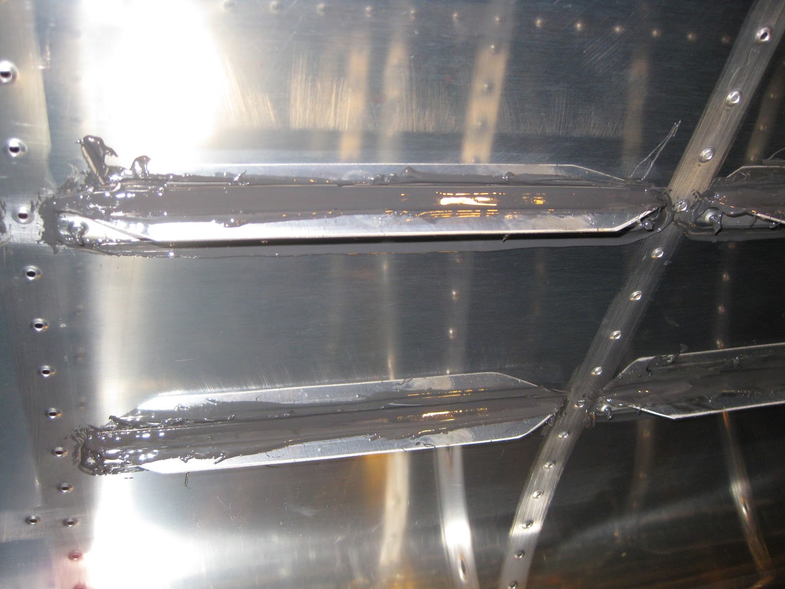
I had dreams of making very clean seals.  That ended quickly, as you can see.  I smeared sealant on with the Popsicle stick.  More is better, right?

Left fuel flange inside and out.  It took a good 15 minutes of cleaning with acetone to get the exposed part of the flange cleaned up.


Left drain flange inside and out.


Some rivets on the exterior.  You can see the small amount of sealant around the rivet heads.  This was even after wiping down with acetone.  So this material was under the heads.  Guess that's the tank die set  (dice?) at work.


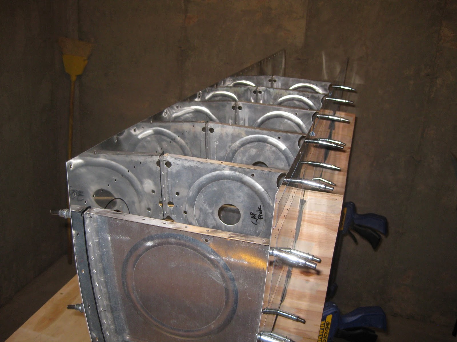
Shop ends, some sealed, some not.


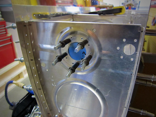
And some stuff on the inboard ribs.  This was after vigorously cleaning the surface since squeezing rivets with gloved hands covered in sealant makes a mess.  The plans state you don't need to seal the nutplates.  But I had extra sealant mixed so might as well in case the seal on the fuel level sender plate fails.  Perhaps it won't matter.  It's hard to say without seeing it assembled.


I believe this is the least fun part of the build.  Can't progress further until I get a riveting partner.  Perfect (?) timing since my rivet gun stopped working.  It just hisses now.  I wonder if it got gummed up somehow on the inside.  I'll run some acetone through the air intake.

29 July 2013

Wings: Fuel tanks. Stiffeners sealing.

I decided to redo my fuel tanks.  See here for why.  The entries specific to the redone tanks are here.

I yoinked a Brecknell PS7 Electronic Postal Scale, acetone (rather then MEK) and Popsicle sticks for the first stage of sealing the tanks this evening.  First I removed the masking tape to expose the scuffed mating surface of the skins.  Then a thorough cleaning with the acetone.


Then it was opening part A of the sealant.  That stuff is super thick!  It doesn't get thinner when mixed with part B.  In fact, I broke a Popsicle stick in it. 


Here's a stiffener with the mixed sealant slathered on (this is called a fay seal) using the syringe gun.  Turns out that gun isn't too useful at this point.  Seems like the Popsicle stick does fine.  Filling the syringe is not as simple as just aspirating the mixture, since it's too thick.  You have to load it with the Popsicle stick.


Weeping holes.  After cleco'ing, the sealant comes out.


All stiffeners in place, every hole cleco'd.  Each one of the stiffeners was reworked with a fillet seal.


Close-up of fillet seal around stiffener.


Fuel flange on both sides (left skin on left, right skin on right) with vent line clip.


Inboard ribs.  Somehow I lost the other T-1010 Anti-Rotation Plates I bought last week, which is why you'll notice the obvious missing pieces.  Can't find them anywhere.  Need to order two more.  I even checked the vacuum thinking I may have sucked them up accidentally.


All-in-all, it wasn't too bad an experience.  I wore my respirator so I couldn't smell anything.  Tomorrow will see me try to back rivet, wet, all the rivets for these parts without help.

28 July 2013

Wings: Fuel tanks. Sealant Prep.

I decided to redo my fuel tanks.  See here for why.  The entries specific to the redone tanks are here.

Following Mouser's approach, all internal parts have been traced around once I had the ribs cleco'd in.  I'm glad I did this since it uncovered that I didn't flute the ribs aggressively enough.  The alignment was so poor that the ribs would not line up properly with the skins.  Following a second shot at fluting, they lined up like butter (is that even a thing?).


The lines looks neat.


The lines are used to define the areas to mask out so that only the mating surfaces are scuffed, in an effort to preserve as much alodine as possible.  Plus, the lines will help delineate the areas where I don't want to sealant to go.  Following the scuffing, it was off to dimpling.  Need to be careful here since there are a few holes that do not get dimpled.


I had my first missed dimple.  The skin was lined up on the die and as I was bringing the DRDT-2 handle down, the skin moved and it was too late (I usually "snap" the handle down in a quick motion in an effort to make a "crisper" dimple).  I ended up opening a new hole partially overlapping the rivet hole.  The left image shows the hole immediately after the error on the exterior.  The right shows the interior after sanding it down (you can imagine it created one heck of a burr) and opening it up to take a Rivet of Shame, NAS1097AD4-3.5.  There's quite a gap around the shank still, so I need to evaluate if this is a reasonable approach to dealing with the issue or if I need to take a different action.  Too bad this happened on a tank skin.


I snagged a manual syringe gun to apply the sealant in what I hope is a cleaner approach.  This idea was shared in this thread, specifically, post 16.  And here's another great thread on sealant application.


Update 3-Jan-14:    The manual syringe gun isn't ideal and it's expensive.  I obtained a Semco sealant gun for more than half the cost.  It is far superior.

25 July 2013

Wings: Fuel tanks. Prepping for sealant, capacitive probes fabricated and locking caps.

I decided to redo my fuel tanks.  See here for why.  The entries specific to the redone tanks are here.

Here are the tank stiffeners, J-stiffener and fuel cap flanges placed in the skins.  I'm tracing around these parts so I know to what extent I should scuff the interior of the skin for sealing.  I'll do the same for the ribs separately.  Since the interior of the tank skin should not be primed, I want to preserve as much of the alodine layer as possible.


Using my new nut plate jig for the capacitive probes I fabricated.


Match drilling the VA-141 Flange, Finger Strainer to the T-1003B-R Tank Inboard Rib - Aft.


Below is the Tank Inboard Rib - Aft showing the location of the optical fuel level sensor I'll be using as a redundant low fuel warner.  I placed it about 1.75" from the bottom of the tank at that location.  A quick, back-of-napkin, entirely inaccurate calculation suggests this will correspond to a bit more than 5 gallons, which ain't much (Update 10-May-18:  It ended up being about 1 gallon as I didn't consider dihedral).  If the warner goes off, it's either time to switch tanks to a hopefully fuller one and/or find a place to put down of my own choosing.

The T-1010 Anti-Rotation Plate is visible on the left.  Also, there is an additional hole at the top which is for the BNC connector that will be used to connect to the capacitive probes.  I've decided to use both the capacitive probes and the floats as redundant fuel level indicators.  This is for two reasons 1) in case one fails and 2) in case my capacitive probes end up being non-functional or not satisfactorily accurate.


And locking caps which fit the stock flanges (I verified this with Robin at Newton SPRL prior to purchasing).  Left image:  Locking cap with universal flange on left.  Right image:  Caps swapped.  I will be using the setup on the right.  And I guess I'll have surplus caps and flanges.


And why not get a "Remove Before Flight" keychain for the associated keys?

Wings: Pitot static. Dynon AOA pitot.

I picked up the Dynon heated AOA pitot and a PBK-12 Gretz Aero bracket.


Read the entries in my AOA series:

21 July 2013

Wings: Fuel tanks. Match drilled, countersunk and low level fuel sensor.

I decided to redo my fuel tanks.  See here for why.  The entries specific to the redone tanks are here.

Work on the tanks continue.  With the leading edges 95% done, I have more space to work on the tanks.  Here are the cap flanges after countersinking them to fit the skin dimples.  I plan to get locking caps.


Tank skins after matching drilling the J-stiffener and now ready for countersinking along the baffle holes.  About 336 holes in fact.  Match drilled, deburred, straightened, dimpled and fluted tank ribs visible, as are my in-progress capacitive probe plates.


And, the original crates are starting to look empty.


Okay, so the flap and aileron ribs and other smaller associated parts are elsewhere, but seems a far cry from the first day with the full crates and all the hardware.

Today marks the 250 hour mark.  I will take a guess that I'm looking at 200 hours to go.  We'll see how this prediction holds up.  Update 10-May-18:  Bad prediction. The wings required 611 hours.

Also, I liked the idea of a redundant low fuel level warning light.  Aircraft Extras has a nice setup, however I could make my own, with the features I want for less, using the same liquid level sensor.  After some digging around, I determined that the Honeywell LLE102000 is similar to sensor used with Gopher Electronics having it for the lowest price.  I picked up two and will also grab two anti-rotation plates for the install.  The sensor is just a simple TTL-type.  Just need to ensure a regulated supply which is easy enough.  I'll be able to integrate the input into a simple microcontroller setup that I plan to have doing various things.


The bottom of the 26-Jul-13 post shows the install of the sensor.

Wings: Leading edges. Left side riveted.

Banged this one out in about 3.5 hours with help.  We had a system down and the mojo came together.  No rivets needed to be removed.  Here are both the left and right parts, parked in comfort until they're ready for the landing light lens fitting (and left side still needs the stall warner).


And here is a great suggestion on how to ensure the lens is properly aligned.  I plan to follow this approach.

19 July 2013

Wings: Leading edges. Right side riveted.

With the gracious help of my friend, we banged out the right leading edge in about 5 hours.  Only had to drill out two rivets (one due to an edge strike on the bucking bar and the other due to the shank folding over).  No Rivets of Shame necessary.  All that remains for this piece is cutting and fitting the landing light lens and fixing one skin hole that I missed dimpling (needs a dimple and a rivet).  We also riveted the access port doubler on the left edge and cleco'd everything together for its riveting fun.

Here is the right side, waiting for its landing light lens.


Here is the left side, cleco'd and ready to be banged out.


And a view down the top of the right (foreground) and left (background) leading edges.


Couple of points:
  1. When cleco'ing the ribs into the skin, start by keeping the skin outside of the cradle and cleco fore-to-aft, alternating top and bottom.  This way the skin tightens around the ribs rather than forcing the skin to mold to the ribs.  Once you get the clecos about 6-7 back on each rib, put the whole piece into the cradle and complete the clecos.
  2. Put a cleco in every hole to make sure all is tight.
  3. Tape the heck out of the edges of the bucking bar to avoid marring any surfaces.
  4. Keep the bucking bar and mushroom set orthogonal to the skin.
  5. You may have to drill out holes to get the rivet to sit straight.  There is a lot of curvature being forced into these parts and not everything will line up initially.
  6. Calibrate the air pressure so about 1.5 seconds of gun burst can fully set a rivet.  Saves lots of time.

Wings: Fuel tanks. Capacitive fuel probes.

I decided to redo my fuel tanks.  See here for why.  The entries specific to the redone tanks are here.

Here in the 21st century, in addition to using floats (for steam gauges), I also want to go with capacitive (for the EFIS).  Turns out for the latter there is no such option for the -14 (though there is for other models).  Since the wing of the -14 is essentially that of a -10, there is quite a bit of precedence for fabricating the probes for the wing.  Here are four examples: Brian's RV-10, hanger52Mouser's RV-10 and of course the amazing Ed (pages 1, 2 and 3).  In fact, Ed's fantastic site includes essentially a stencil for the plates.

I printed his out after scaling it properly, precisely cut the paper with scissors and lined up the shape on my tank ribs.  Sure enough, it's a perfect fit.  So I bought the capacitive kit from Van's for the -9 so I can get all the parts then planned to fabricate my own plates using Ed's stencil (since I naturally won't be using -9 plates as they aren't the right size).

I purchased an 18"x16" section of AS3-020 from Van's and cut it down to four pieces 9"x8" each.  I drilled holes on the perimeter and where the mounting nutplates would be then attached clecos to hold each piece together in a stack.  Then, I taped the properly scaled stencil to the stack.  Running it carefully through the band saw, I got the following ("reassembled" to show the original setup):


Then after filing things down a bit (still needs more smoothing of the edges), I ended up with a stack of four nice capacitive probes.


I also got a nutplate jig so I can properly place the mounting nutplates on the probes.  I still need to drill out holes for the wires and fabricate some covers for the stock fuel level sender holes in the ribs (covers the holes for the float apparatus).  See Mouser's picture for reference.

See here for installation on my original & replacement tanks.