Left and right flaps have their top skins on, save just a few rivets each.
Below are the left rod end subassemblies. Yes, on the inboard one I foolishly match-drilled and countersunk for a non-existent nutplate. Consider them lightening holes.


It's not easy to squeeze some of the ribs onto the spar since other immediately adjacent ribs impede access. Below is my suggested sequence and method of setting the rivets on those ribs that are crowded out a bit.

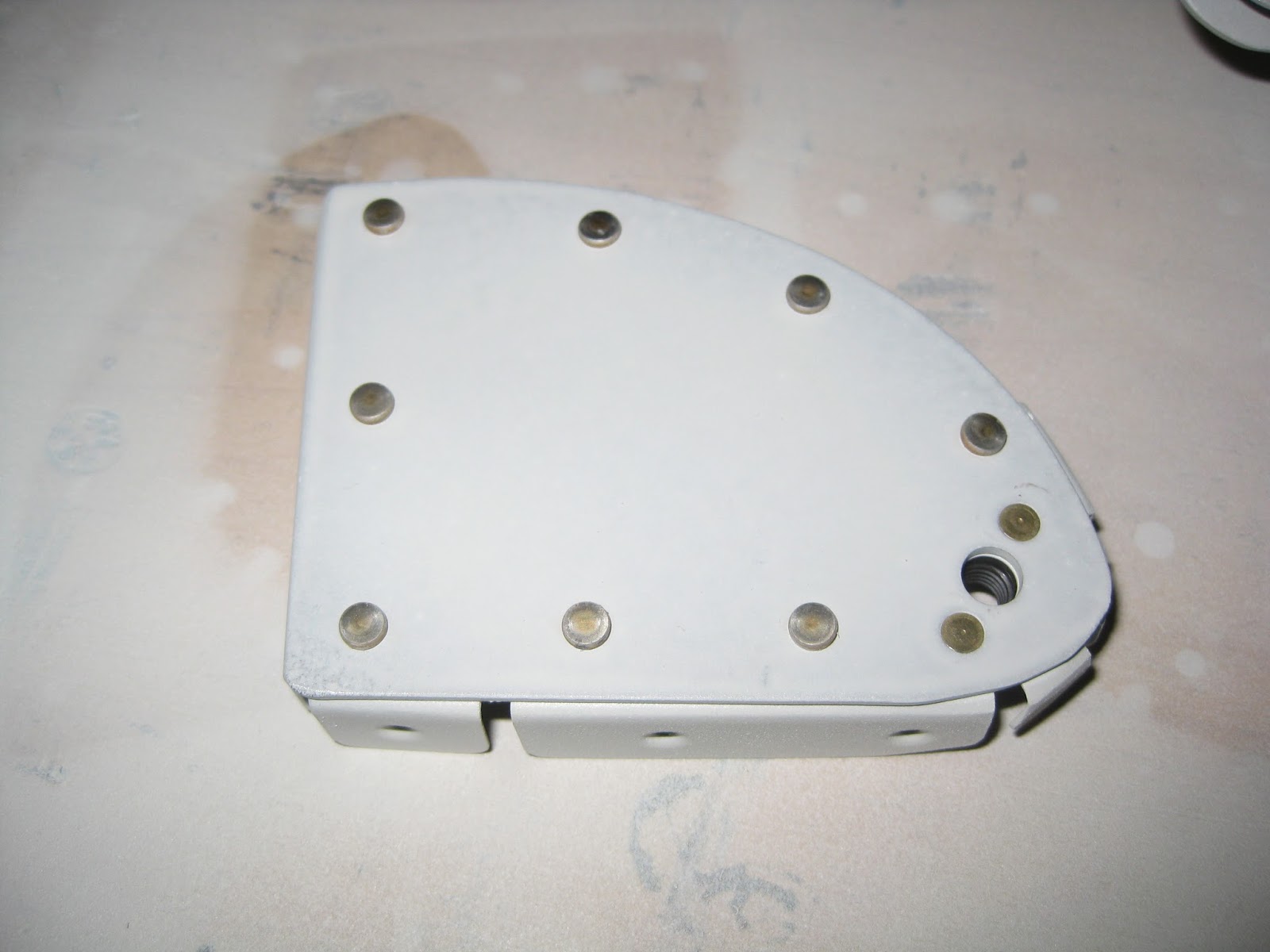
Left inboard hinge pair subassemblies. The main rib's rivets were bucked.

Unfortunately, I initially tried to squeeze the outboard rib's rivets. The middle rivet was easy, but the flanges separated slightly around the rivet shaft. In order to access the upper and lower rivets I had to bend the main rib quit a bit. Though the plans mention that such an approach is acceptable, you have to consider that the flange will be pulled from being flush against the spar. This means a potential space between the spar and rib flange opens up and becomes an actual space for your rivet shank to have a party in and fill. The left image is how that comes out. Look at the left and right rivets - no narrative necessary. The right side is what it looks like after I pulled out the rivet on the left (which is the bottom of the spar) and instead bucked it. You can see that the removal process (a challenging affair given the limited access) elongated the hole so the replacement rivet doesn't sit in there nicely: The shop end is short and now the spar is slightly deformed.


I deemed that unacceptable. Now, removing those left and right rivets wasn't going to be easy a second time. The holes got even worse. Here are the holes with a AN470AD4-5 (plans call for a -4) rivet placed in them.


An AN470AD5 nearly fit in them. I didn't want to put that large of a rivet in there since I only have a 2x gun, don't have a rivet set for it and the flanges didn't need the additional stress from trying to buck such a rivet. So for each side, I took an AN470AD4-5 (again, the plans call for a -4) and pre-squeezed to fit just snug in the hole. Below are two pics showing, right-to-left, an AN470AD5-5, my pre-squeezed AN470AD4-5 and an AN470AD4-4. This gives a good indication of how large I made that hole.


Here is the left side with the pre-squeezed rivet place in the hole. It's a better fit, but isn't perfect.

I could then bend the spar back and get a better fit with all the flanges together. The left image is from the left flap after (the now second) replacement with the pre-squeezed rivets. The right image is the right flap in same place showing what things look like when you get it correct the first time. Given the three layers coming together, looks like I should just have bucked them all on the right side. That middle squeezed rivet separates out the flanges.


I'm pretty sure I'll be removing the two left flap rivets and just drilling up to an AD5. I don't like how it all sits. The right looks okay, save for that middle rivet which I can straighten up.
The hinge pair subassemblies call for the rivets along the joggled end to be riveted double flush. I initially tried to buck these double flush rivets but because it's very hard to keep the subassembly flush against the backing plate, they didn't sit nice and it was too easy to injure the part with the rivet set. So, after sanding out the damage I caused, I decided to squeeze all of the double flush rivets on the joggles. Having never done that before, I was pleased with the outcome. Unless you look really close, you might have a hard time distinguishing the factory (left) and shop (right) heads. Tip: If you screwed up a machine countersink on one side of the joggle, just put the shop end in that countersink. Problem solved!


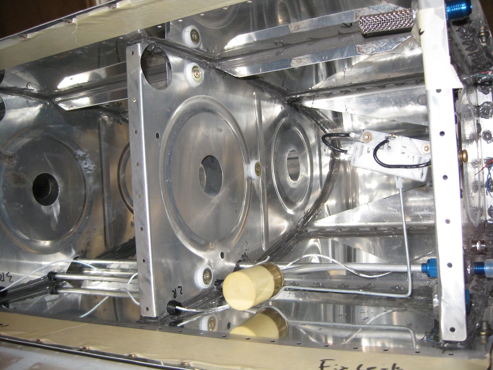
Left and right flap skeletons ready for skins.


Here the left flap sits with the top skin cleco'd, ready for riveting.

Right flap with most of top skin riveted. The inner AN426AD3-4.5 rivets have yet to be bucked. I decided I wanted a bucking partner for those. Too easy to damage the factory heads on the main rib rivets when going solo. Also the aft two-most rib rivets need to be back-riveted.

Left flap in same state parked in the (nearly empty!) wing crate next to a bottom flap skin and aileron skins.

Below are the left rod end subassemblies. Yes, on the inboard one I foolishly match-drilled and countersunk for a non-existent nutplate. Consider them lightening holes.

It's not easy to squeeze some of the ribs onto the spar since other immediately adjacent ribs impede access. Below is my suggested sequence and method of setting the rivets on those ribs that are crowded out a bit.

Left inboard hinge pair subassemblies. The main rib's rivets were bucked.

Unfortunately, I initially tried to squeeze the outboard rib's rivets. The middle rivet was easy, but the flanges separated slightly around the rivet shaft. In order to access the upper and lower rivets I had to bend the main rib quit a bit. Though the plans mention that such an approach is acceptable, you have to consider that the flange will be pulled from being flush against the spar. This means a potential space between the spar and rib flange opens up and becomes an actual space for your rivet shank to have a party in and fill. The left image is how that comes out. Look at the left and right rivets - no narrative necessary. The right side is what it looks like after I pulled out the rivet on the left (which is the bottom of the spar) and instead bucked it. You can see that the removal process (a challenging affair given the limited access) elongated the hole so the replacement rivet doesn't sit in there nicely: The shop end is short and now the spar is slightly deformed.


I deemed that unacceptable. Now, removing those left and right rivets wasn't going to be easy a second time. The holes got even worse. Here are the holes with a AN470AD4-5 (plans call for a -4) rivet placed in them.


An AN470AD5 nearly fit in them. I didn't want to put that large of a rivet in there since I only have a 2x gun, don't have a rivet set for it and the flanges didn't need the additional stress from trying to buck such a rivet. So for each side, I took an AN470AD4-5 (again, the plans call for a -4) and pre-squeezed to fit just snug in the hole. Below are two pics showing, right-to-left, an AN470AD5-5, my pre-squeezed AN470AD4-5 and an AN470AD4-4. This gives a good indication of how large I made that hole.


Here is the left side with the pre-squeezed rivet place in the hole. It's a better fit, but isn't perfect.

I could then bend the spar back and get a better fit with all the flanges together. The left image is from the left flap after (the now second) replacement with the pre-squeezed rivets. The right image is the right flap in same place showing what things look like when you get it correct the first time. Given the three layers coming together, looks like I should just have bucked them all on the right side. That middle squeezed rivet separates out the flanges.


I'm pretty sure I'll be removing the two left flap rivets and just drilling up to an AD5. I don't like how it all sits. The right looks okay, save for that middle rivet which I can straighten up.
The hinge pair subassemblies call for the rivets along the joggled end to be riveted double flush. I initially tried to buck these double flush rivets but because it's very hard to keep the subassembly flush against the backing plate, they didn't sit nice and it was too easy to injure the part with the rivet set. So, after sanding out the damage I caused, I decided to squeeze all of the double flush rivets on the joggles. Having never done that before, I was pleased with the outcome. Unless you look really close, you might have a hard time distinguishing the factory (left) and shop (right) heads. Tip: If you screwed up a machine countersink on one side of the joggle, just put the shop end in that countersink. Problem solved!


Left and right flap skeletons ready for skins.


Here the left flap sits with the top skin cleco'd, ready for riveting.


Left flap in same state parked in the (nearly empty!) wing crate next to a bottom flap skin and aileron skins.

And just to be complete, here are the backsides of the right and left flaps.