25 February 2015

Fuselage: Forward mid fuselage side structure. Longerons continued.

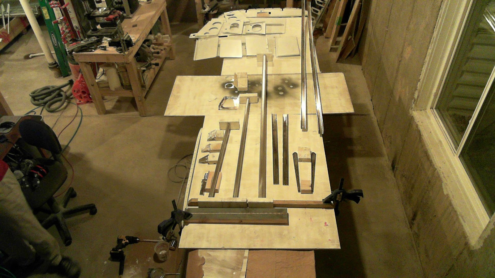
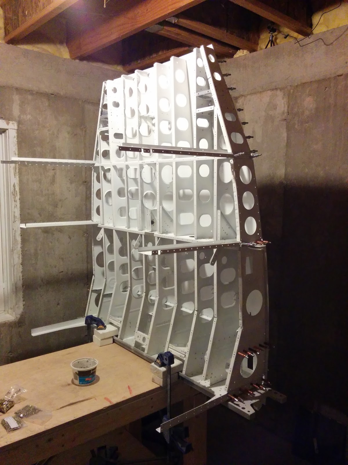
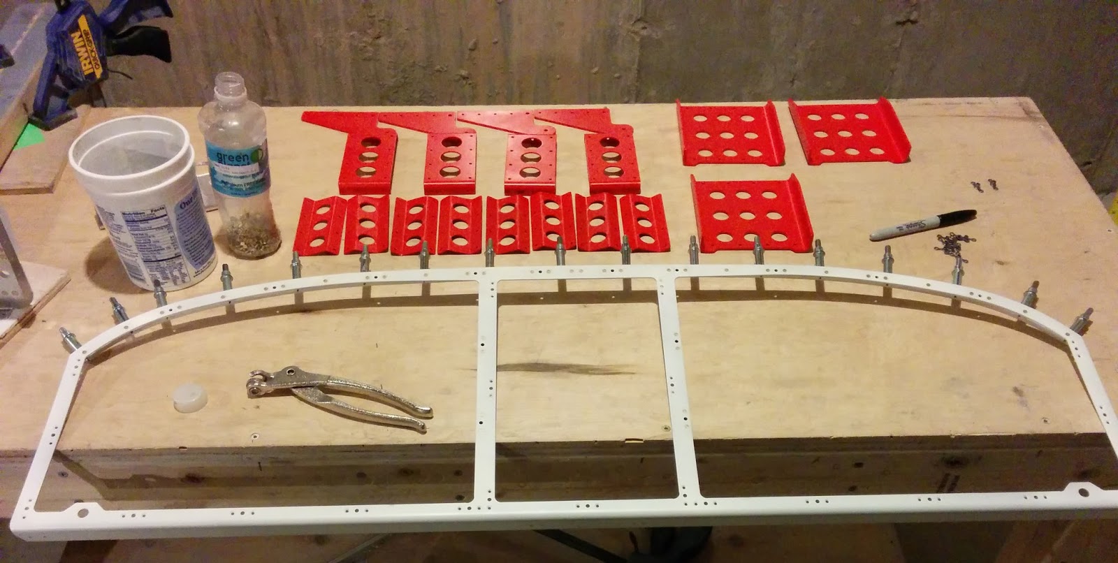
Following the original preperation of the F-01418A-L/R upper longerons, it was time to continue their plight.

On first look, the F-01488-L/R upper engine mounts seem identical.  However if you inspect them carefully, you'll notice the forward face has a very slight angle to the vertical.  Stare at it long enough and you'll see it.  So, it's easy to interchange these parts even after match drilling.  I happened to lose track of -L/R during priming.  Below is a disambiguation image provided to me by Van's.  Note:  In the image, the part is oriented upside down relative to installation.


Below shows the right side mount upside down (bottom side facing upwards) with its forward face against a 90 degree edge.  You can see the 90.6° angle subtly subtended by the two edges via noting the progressively larger gap going upwards.


Left F-01418A-L upper longeron and engine mount installed, top (left) and bottom (right).
 

Right F-01418A-R upper longeron and engine mount installed, top (left) and bottom (right).  The forward-most CherryMax on the top (left) isn't ideal however it does meet the spec (page 14 of the CherryMax Process Manual).


Now for the F-01444-L/R lower longerons, it's easy to lose track of which side is left and which is right when dealing with the longer doublers F-01444A-L/R, especially once you separate them from themselves.


I had fastidiously labeled each side, but following the priming process, like with the upper engine mounts, I lost track.  Luckily, I had some pictures of a fuselage in progress at Van's which made it clear to me how to orient the parts (further confirmed on VAF).  Below shows the proper way.


When I went to put in the CR3213-4-5 CherryMAX rivets, having little experience with them and being calibrated to standard AN426/470AD4s, I thought the Cherrys(ies?) looked too short for the material thickness. 


After learning about CherryMAX rivets from this Cherry Aerospace pdf, I found that the "-5" indicated a maximum grip length of 5/16".  Measuring the thickness of the parts found 0.285" which is 4.56/16".  Thus a -5 is the appropriate length given that the next smaller size is -4, making it too short.

Completed lower longeron assemblies showing the F-01489-L/R lower engine mount brackets.  Interesting CherryMAX shop heads.  They appear to be acceptable (page 14 of the CherryMax Process Manual).


22 February 2015

Fuselage: Forward mid fuse bulkheads. Forward center completed.

Remarkably, I finally completed the forward center bulkhead.  What was holding me up was my third and finally successful attempt at the right bearing bracket assembly.  See here for details on try #1 and here for try #2.

It is my suggestion to rivet the F-01441-L/R bearing bracket braces to their respective inboard F-01438-L/R cover ribs prior to riveting those ribs to the F-01403 forward center section bulkhead.  The plans have you rivet the braces after the cover ribs get riveted to the bulkhead.  That makes accessing the rivets holding the braces to the ribs difficult (see below).  I see no impediment to accessing the rivets holding the cover ribs to the bulkhead with the brace riveted on beforehand.


I have no isolated picture of the completed bulkhead, as I attached it to the lower forward fuselage prior to thinking of capturing an image.


21 February 2015

Fuselage: Firewall. Forward assembly, tunnel and center completed.

The firewall comes together.

I didn't bother to look at how well the F-01401G-R and F-01401D firewall angles laid up.  The left side fit fine (left).  But the right side did not (right). 


I observed this after the sealant cured and after 3 rivets holding the F-01401D angle were set (left).  So I had to drill them out to get the parts to lay up properly.  The angle could easily pop up under minimal flex, so when I added the F-01401J angle and F-01401R gusset, the clecos kept it down.


The sealant  needs to cure before final riveting commences.  So here it had to sit for a week or so.


Sometimes I needed to cut away the sealant bead at the joints of the parts, otherwise I couldn't get the mushroom set to have a flush surface to buck against (the second-from-left rivet manufactured head looks bad but it's actually okay).  This bead was a consequence of using too much sealant at the joint between the F-01401A firewall top and F-01401B firewall sides (see below).  To mitigate this issue in subsequent steps, when sealing in the F-01401C firewall center, I smoothed down the bead immediately following sealant application (see upper left image)


I found it impossible to buck the rivets at the gusset.  Well, that's not true.  I couldn't buck any single rivet since they were so closely spaced.  I could have back riveted, but the rivets were slightly oversized, leading to a significant clenching-over risk.  Determined to find a way to squeeze as many as I could, for the outboard rivets, I used my longeron yoke.  For the inboard ones, I used the 3" yoke with a 1/4" tall squeezer set.  This, combined with folding in the flange on the firewall top, allowed me to reach in deeper (see below).  The inboard-most two rivets had to be bucked, which was completed with the help of a friend.  I could have used my  4" deep yoke, but I was concerned the rivets would clench under the yoke's flexing.


Curious when these two boys get riveted, from page 27-07 (left)?  It happens on page 29-14 (right).


Bucking the rivets at the nose gear brackets is tough.  Because the part is steel, it absorbs a lot of the impact energy from the rivet gun, robbing the bucking bar (Mr. T!) of its efficacy.  I had to use 100 psi on my 2x gun.  The bottom rivets were instead squeezed with the longeron yoke.


After much generous bucking help from a gracious friend, here's the firewall, completed.


A few places need spot-priming on the aft side due to the sanding out of minor bucking bar scuffs.


This is a rivet map showing which rivets I was able to squeeze (green) and which had to be bucked (red), either classically or via back-riveting.   I found that some upper row AN426AD4-6 rivets on the upper angle F-01401J were too long and clenched over too easily.  Using my rivet cutters to create a batch of -5.5 length also caused clenching due to the way the rivet shaft is sheared.  So I sourced a legitimate batch AN426AD4-5.5 rivets (actually MS20426AD4-5.5) yielding great results.


One of my blog readers indicated to me that he back riveted his entire firewall by placing the assembly face down on an undersized table (otherwise the flanges would lift the assembly off the table).  I think that's a great idea, especially if you're going solo.  I tried it for a few rivets but my shop just wasn't equipped to adequately realize that approach.  I share his approach hoping that someone will find it useful.

18 February 2015

Fuselage: Multiple sections. Priming.

Routine priming of some parts.  Nothing exciting.  Longerons, instrument panel parts, vent brackets and pushrods.


Primed.  As usual, I used my HVLP gun and two part epoxy primer.


17 February 2015

Fuselage: Mid fuse lower structure. Baggage ribs to skin.

The baggage ribs have been riveted to the F-01484 bottom center skin thanks to help from a friend.

The assembly sat ready for the process on a bed of its own clecos.


As with the seat ribs, we kept the assembly vertical as it lent itself well to the riveting process.


It wasn't too burdensome to reach the rivets.  The deltoids indeed accumulated a surplus of lactic acid during the high reaches.


And here is the completed assembly.  Section 26 is officially complete.


03 February 2015

Fuselage: Rudder and brake systems. Rudder pedals.

Not only am I out of space, the weather is not conducive to priming.  So I progress through the plans, match/final drilling, deburring, etc., collecting a large pile or prepared aluminum awaiting a turn through the priming process once the snow departs and the sun returns.

To that end, I got to cleco'ing the rudder pedals together for match drilling on 26-Dec-14.  They feel mighty stout.


After seeing this guy's pedals, I decided to paint my pedals red using Rust-Oluem Painter's Touch poppy red satin finish from Airplane Depot.  I finally got around to that on 27-Jan-15.  The parts looked nice once painted, after scuffing and acid etching (yes, the instrument panel frame in-progress is front-and-center - working ahead to make use of the time and space as best I can).


And here are the completed left side rudder pedals and one right pedal (the other needs repainting since I dropped it and ruined the finish, thankfully before any riveting).  Not sure I like the gold-on-red at the rivets, but no one will care, other than me, apparently.  Because all of the rivets are universal head or LP4-3, the squeezer/puller doesn't upset any of the paint.  Hopefully the paint will hold up because I doubt they'll ever be repainted once installed.


The right, right rudder pedal's paint was easily removed after soaking it in acetone for 6 hours.  The paint mostly sloughed off on its own during the soak.  What remained was easily removed with an acetone-moist cloth.


It's interesting to note that the prototype RV-14A, N214VA, has a different set of pedals on each side.  The left side (left) has the same pedals as included in the kit.  The right side (right) has pedals from what seems like their other models (I took these pics back when I visited Van's).