17 July 2015

Empennage: Aft empennage. Top side and top skins on. Finally.

It was on 4-Jul-14 that the bottom side skins were attached to the aft fuselage.  At that point, the structure could no longer accommodate the top side and top skins as it would have made it too big to remove from the house.  Thus, following the addition of various cables, rudder guides, static plumbing, bulkhead riveting and the aft deck, the structure imposed as an unwelcome couch-surfing roommate in my living room, along with the wings, until the future (now current) new house could offer the structure the space it beckoned for.  I cleco'd the top skins on just for looks.  They had to be removed so the structure could fit through the door when I moved to the new house.


And so, a little more than one year later, on 17-Jul-15, a gracious friend spent 4.5 hours with me to rivet the structure to near completion.  Just a few rivets remain, including some match drilling for the vertical stabilizer (page 10-28) and this bad boy will be ready for attachment to the forward fuselage.  Sections 11 (Empennage Attach) and 12  (Empennage Fairings) can be completed with the tail attached to the fuse.

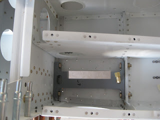
The rivets along the longerons and bulkheads were bucked classically with a flat set and bar.  The rivets attaching the top and top side skins were back riveted with me sprawled out in the structure.  The picture of me inside the tail cone is less than modest, so it's left to the reader's imagination.  However here is one showing my wayward hand poking out from the inside of the tail onto the aft deck.  You can also see the fuselage right side skin ready for riveting.


In hindsight, we should have done all of these top half rivets by back riveting with me inside the tail cone.  I was hesitant to do it given how imposing it seemed.  Other than the bearable discomfort of the protracted time in a confined space limiting my movement, it was easily accomplished.

Here is the nearly completed aft fuse.


In case you're wondering why the aft bulkhead no longer seems complete, see this post.


12 July 2015

Fuselage: Forward mid fuselage side structures. Side skins ready.

Getting the side skins ready for install.

F-01470-L/R side skins get cleco'd for various match-drilling needs.


The F-01418A-L/R upper longerons get countersunk.  This is the left longeron.  The holes will need to be re-primed.  The lower longeron gets the same exercise (not shown).


The F-01485-L/R side plates get countersunk.


FF-00006B-L/R cowl hinges get countersunk.  See my later post for my thoughts on these hinges.


I back-riveted the side plates and F-01464-L/R to the side skins.  It's important to keep things clamped down lest the rivets find themselves prideful.  I used AN26AD4-7.5 instead of the -8s called for in the plans.  The -8s were too long and kept clenching over.  I also used AN426AD3-4 on the rivets holding the side plate to the skin rather than the called out -3.5 as I felt the latter were too short.


10 July 2015

Fuselage: Forward mid fuselage side structure. Firewall wasn't straight. Now it is.

When the upper longerons are placed against the firewall (page 29-08), the upper engine mounts should lay flush against the firewall gussets F-1401L. The right side clearly did not. Only the lower inside corner of the engine mount made contact with the gusset. This meant that the engine mount wasn't straight relative to the firewall.

Looking from top, left on left and right on right.


Further inspection revealed that the two aluminum angles, F-01401D and F-01401J, that compose the upper C-channel of the firewall have a curve in them. They are not straight. A straight edge laid across the top of the firewall illustrates this curvature (convex with respect to the aft side).


A call to Van's yielded the suggestion that I use a bottle jack and 2x4s to take out the bow.  I lack the skills to make that happen (in fact, it's worth questioning whether I have any skills at all).  It turns out, another  builder of an RV-14A that I'm in touch with is a shop-master. He owns and operates a very well-equipped machine shop.  He very kindly came up with the following contraption to straighten the upper firewall C-channel.

It's a steel support bar with three points of contact on the firewall. Two are the upper engine bolt holes with Delron standoffs. The center point is just a thick threaded screw with its head cut off, placed in a Delron sleeve to prevent marring of the C-channel's surface. As that screw is advanced, it pushes the center of the C-channel, whilst the outside screws hold the C channel's edges back. Let's call this device the Clifflatron.  Here it is in place ready to do its dirty deed.


It took this much bow, about an inch at the center, to take out the firewall curvature!  And yes, this was not an easy to task to do only because I was waiting for the explosion of overstressed parts. 


And now the firewall is straight.  Left is pre-straightened. Right is post-straightened.


One would think that the issue with the engine mount is solved now that the firewall is straight.  It wasn't.  In fact, there was no change!  Left is pre-straightened. Right is post-straightened.  I can't explain it.


When the temporary 3/8” bolt is tightened, the gusset and angles deform a little bit and ultimately conform to the engine mount, closing the gap.  I've accepted this and moved on with the build.


03 July 2015

Fuselage: Forward mid fuselage side structure. Mating forward and lower fuselage structures.

Building resumes some three months following the move to the new house!

Page 29-02 sees the start of the mating of the forward and mid fuse lower structures.  This first occurs with a band of clecos running under the bulkheads.  This is easy enough to accomplish by one's self, so long as the structure is up on blocks.  Next the U-01402 gear braces are bolted in along with the F-01442-L/R lower and F-01464-L/R upper drag fittings.  I had a heck of a time getting the left gear brace to fit.  In fact, I had to sand the gear brace assembly down to get a good fit.  Then it was a good solid hour to get the bolts tightened down (which subsequently get removed and replaced later for rivet access).


Some good #40 match drilling begins of the upper drag fitting to the F-01485-L/R center section side plates.  This is later repeated for upsizing to #30.


I had a hard time finding the right thickness wood for the support leg.  I ended up finding three different boards at Lowe's that, when stacked, gave the right thickness (left).  So it was time for a little aerobatics in the shop (right).


After spending an hour-and-a-half pulling -5 Cherry rivets into the lower drag fittings (a process that  each ends in what is aptly described as an explosion with the projectile launching of the stem and washer vaulting across the shop) and dealing with the protestations of my forearms, I noticed that I neglected to set a rivet, back in Section 26, attaching the F-01484 center bottom skin to the F-01415-L/R outboard seat ribs (left).  Whoops.  I sneaked a rivet in underneath (technically on top) of the F-01483-L/R forward bottom skins in (right) and opted to buck them through the skin.


With the generous help of a friend and a ladder, 2.5 hours later, the sections were mated with their associated rivets.  The bolts attaching the gear supports and lower drag fittings were decimated during their removal.  I'll be replacing them to the tune of $30.


Then it was some 3 hours of getting the control column assembly to rotate with little friction.


After several trials of fitments and sliding washers in (dangling them stuck to masking tape), I had to bend the ears of the control column assembly to straighten them up.  The ultimate washer stack ended up being two NAS1149F0363 on the left inboard and single 363 and 332 washers on the left outboard (left).  The right side had two 363 washers with a single F-14146A shim (sandwiched between the washer so it won't contact anything) on the outboard side and a single 363 with the same size shim on the inboard side (right).  The control column assembly very nicely rotates with no noticeable friction.  I'm confident of this as the hours it took to get to this point included fitments with levels of frictions from great to small.