21 February 2017

FWF: Exhaust System. Exhaust placed.

It turns out that the EX-00006 Tailpipe System (the center exhaust pipe under the tunnel) absolutely cannot be fit into place with the nosegear leg in place.  I tried for an hour trying to convince myself otherwise.  Instead, it requires using the engine hoist to raise the airframe an inch or so off its nose wheel.  Let's call this a "negative G maneuver".


After lifting the airframe off the nosewheel, the U-01416 Nose Gear Link Assembly must be released so that it can be swung forward.


Only then can the EX-00006 Tailpipe System be placed.


This shows the F-01469 Tailpipe Hangar Links attached.  Those links should probably have been primed.


Finally, all exhaust parts are installed on both sides of the engine. 


15 February 2017

FWF: Cowl Baffle. Cowl baffle seals placed.

This was an easy task.  Nothing exciting to report here.  Just placement and riveting.  I have not yet applied RTV to seal gaps or to secure the magneto blast tubes.  I'm waiting to finish all work on the cowl halves.


14 February 2017

FWF: Cowl Baffle. Snorkel completed.

The VA-132-2 Snorkel actually takes a significant amount of work to complete.

First, the cap for the fuel injector is removed (left) then the fuel injector is mounted (right).


The Snorkel is man-handled into place and clamped down.


Then the outline of the fuel injector's flange is traced onto the Snorkel's flange to ensure it is centered.  Then, using a template provided in the kit, the round flange is cut into the square shape necessary to fit the injector servo.  The picture below shows how well the pieces were centered and the good, clean trimming of the flage.


Next the top of the Snorkel is cut to length (not shown) and match drilled into the CB-00020 Air Filter Frame.


Then the two pieces are properly adhered to each other with an epoxy-flox mixture.


Next a 2.75" diameter hole needs to be cut into the left side of the Snorkel to accommodate the alternate air input system via the V-192A Alternate Air Inlet.  I used a hole saw with very light pressure (left) and obtained great results.


Here is the crimp on the Alternate Air Inlet showing the fit of the VA-192B Filter Bypass Door.


The Alternate Air Inlet is properly epoxy-floxed into place.


A gasket is necessary to seal (left) to seal the Snorkel to the fuel injector (right).  I replaced the one that was installed on the crated engine. That part number is 77504 and is available from Aircraft Spruce.  The gasket was lubricated with oil, the Snorkel installed and the bolts were later safety-wired.


Next the CB-00034 Right Air Ramp Cone must be bent into shape.  First the template is adhered to the aluminum piece (top left) then it is slowly bent into the cone shape (top right, bottom left) until the piece conforms properly (bottom right).


The cone is then match drilled into the CB-00007 Right Air Ramp (left) and riveted into place (right).  I will probably later remove the rivets around the Vent DL-03 and Vent Screen 3x3 and replace with news that have their manufactured heads on top.


A similar exercise is done on the right, yielding a properly fitting CB-00020 Air Filter Frame.


Here is how the alternate air inlet is ultimately situated prior to attaching the cable.


02 February 2017

FWF: Cowl Baffle. Baffles placed.

I completed assembling the baffle parts in April 2016, as I sought to get ahead of future work.  It turns out that I was 10 months ahead of myself, as once I finished assembling them, I set them aside until February 2017 to attach them to the engine.

The baffling was quite straightforward to complete.  Sometimes I needed to get creative with a makeshift "jig" to rivet the pieces together (images from April 2016).


A couple of images showing the aft baffles in their completed states.  As is obvious, I decided to prime the parts simply because I've been priming everything.  The color matches "Lycoming Gray" pretty well too.


The CB-000333 Air Filter Frame Cover is cut, drilled and nutplates are attached.


Moving on to February 2017, I masked off the areas needing RTV.  The primer was then removed and the metal scuffed to give the RTV something to bite on to.  This is the left aft baffle.


This is the left aft baffle.  Note, I neglected to add the strip of RTV on the right side, which I later added.  I realized later that the RTV is intended to prevent chaffing, so it's better to let the RTV cure after application prior to attaching the baffling to the engine.


Here are the forward baffles with the RTV.


Generally, the baffles fit well.  The left aft baffle took a few hours for me to finagle.  I had to bend a tab to get it to fit (it's the tab just under the left nutplate).  The left forward baffle took a lot of on-and-off fitting.  I had to file down the tab shown below by quite a bit.


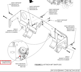
On page 47-07, the little standoff highlighted in red is left up to us to fabricate.  Mine measured 1.031" for a perfect fit.  Go here to see how I made sure that the cut surfaces were perpendicular to the axis of the spacer.


Here are the baffles in place.


Next major step to complete is the snorkel.