28 April 2018

Maintenance: Oil change 2.

Second oil change at 35 hours.  The first was at 12.6 hours.  Everything with the oil, filter and screen were fine.  It's nice not to have any surprises with those.

I found a few tiny leaks in the oil return lines.  See below.  I snugged the hose clamps up a bit and will see how they look at the next oil change.


The starter released a bunch of grease onto the snorkel.  Below is where the bottom of the starter meets the snorkel.   I'll keep an eye on things.  Update 20-May-18:  The starter failed at 43 hours.


I found a tiny fuel leak on VA-168 Sender Mount at the F 1/8 Pipe Plug.  I disconnected the three items on that part of the sender and thoroughly cleaned out the Form-A-Gasket being very careful not to contaminate the fuel lines.  I reinstalled everything and instead used high temperature thread sealant suitable for fuel.


The FF-00076 Sniffle Line Bracket was again broken.  It broke before the first oil change too.  I guess it can't accommodate the twisting of the engine on start?  I replaced it again with a slightly different orientation.  I'm not convinced it's even needed.  Update 14-Nov-18: I fabricated a bracket from 4130 steel stock.  See my post outlining my first annual.


I replaced the Adel clamp holding the aft end of the sniffle line with a MS21919DG9 since the DG10 wasn't holding it tight enough to prevent leakage where the FF-00082A Sniffle Line hose and FF-000083 Sniffle Line Extension mate (maybe my flare wasn't a good one).  Below shows the area from page 49-18.


If you look closely, you can see that the original DG10 clamp is a bit loose.  The DG9 offers a tighter fit.

 
Here's what the leak causes on the U-01013B Wheel Fairing Rear (back of nose wheel fairing).

25 April 2018

Fun Stuff: Quick performance numbers.

I'm still determining the performance of the aircraft I built.  Below are a couple of screenshots from the EFISs in flight showing the instruments.  

At this point, I have the wheel and leg fairings attached.  I picked up 18 KIAS with those fairings (a welcome surprise).  When flying without those fairings, I did not require rudder input during cruise.  However, as can seen below, with the fairings I now need left rudder to maintain coordination.  I will need to pull each wheel/leg fairing off in succession to find out which is/are pulling me to the side and investigate reorienting the offenders.  Maybe I'll pick up a knot or two if I fix it.
  • 158 KIAS, 177 TAS
    • At 58°F OAT, 24.1" MAP, 2500 RPM, 11.7 GPH (around 50° ROP EGT), density altitude 7,752', solo (I'm 165 lbs) with 34 gallons avgas on board and about 5 pounds of tools in the baggage area.  My airplane is fat, with a BEW of 1,312 lbs.
    • I don't know if I built a fast or slow plane or how it compares to other builders.  It would be interesting to see other numbers and consider reasons for variations.
  • Without fail, at cruise I see a 60°F spread between cylinders 2 and 3.  Cylinders 1 and 2 (the front pair), are always hotter than 3 and 4 (the back pair).  I think this is because the rear cylinders get airflow over their tops and rear.
  • I've tried several and, in my opinion, hot starts are easily managed using this technique:  Throttle cracked, mixture full lean, don't hit the pump, crank starter and slowly richen the mixture until the engine catches (reach full rich within 10 seconds, which is the max rated on time for the starter), then move slightly more rich, then pull back throttle to where you want to idle.  Every time I've done this, the engine starts on the first try.
I will post more performance data as I accumulate them and have confidence in their validity.


Avionics: Canopy cam(s)!

I have two inputs into my GMA-240 intercom (which was replaced with a GMA 245 on 12-Aug-18)Music 1 is on the panel (left) and Music 2 is in the center section between the seats (right).  I use Music 2 as an input for tunes from my phone via a Tunai Firefly Bluetooth receiver (below, center). 


But, I also have an output from the GMA-240 intercom, which I placed on the right side of the panel and labeled Music 1 Out.  My plan was to use this for my GoPro camera underneath the canopy.  I initially ran the audio wire from the panel (left) alongside of the seat and up to the camera (right).  Then I powered the camera from the USB socket in the center section.  This worked great, but as can be seen in the right picture below, in order to open the canopy, you have to unplug everything and the wires are dangling right next to you.


I wanted the audio wire to be run out-of-the-way, like within the canopy rail (as is done for the canopy switch on the left side) plus run to power the camera alongside the audio wires.  That would be a total of 5 wires (3 for audio, 2 for power).  The canopy rail just doesn't have access within it to accommodate that many wires.  So the next best thing to do was run the wires within the cockpit along the C-01427-R Aft Canopy Rail Flange and C-1409-R Aft Canopy Rail Angle.  Thankfully, I still had an unused position on my fuse block so I could keep the camera power on its own fuse.

Also, I wanted to preserve the utility of my Music 1 Out jack on the panel, so I fashioned a Y-adapter with one end going to the panel jack and the other leading the to camera.  This bolus of connectors is shown below.  Also note, that the I included 47k-Ohm resistors on the audio lines to attenuate the output level as appropriate for the camera or any other recording device.


Below shows the routing of the 5 wires. I used a very thin, 10 foot audio cable, cutting off one of its ends and attaching the associated Molex connector on that side so I could plug it in to the Y-cable shown above.  30 gauge wire is a joy to strip and crimp and remains extremely fragile, so I made a strain relief out of a bolus of siliconized latex as can be seen above (where the flat red cable meets the Molex connector).  I also twisted the power wires with my drill to reduce radiated interference from DC-DC converter (the converter is explained further below).

First, they run up the C-01417 Canopy Frame Close-Out and C-01403-R Mid Canopy Frame then along the C-01415-R Fwd Intercostal...


...then through the relief hole in the C-01404 Support Flange and along the Aft Canopy Rail Flange and Aft Canopy Rail Angle, tacked down with clear silconized latex caulking...


...The wires are then routed behind and along the C-01405-R Canopy Frame, again tacked down with clear siliconized latex caulking....


...then ultimately to the camera.


But, GoPro cameras are powered from USB, so I needed to bring the 12 V airframe bus voltage to the 5 V of USB and provide a USB socket.  So I designed a very simple circuit based on a tank of a switching converter:  The RECOM RPP20-2405SW.  This thing is capable of pushing out 4 Amps at 5 V from 9-36 V input, has a heavy ribbed case for heat dissipation and is highly efficient (950 mA in at 4 Amp out with 89% conversion efficiency at full load).  It's operating temperature range is well outside of anything it would ever experience in my plane, even in full sun at full output.  I am confident it can handle the airplane environment nor should it melt (melting a hole in my canopy in flight).  Plus, it has integrated EMC filtering to Class B standards.

The board I designed for my simple circuit (using KiCAD and sent for fabrication at a nearby board house) accepts the converter, two USB plugs, four ceramic filter capacitors (for extra noise cleaning) and three holes.  I wanted the board to be mounted as close to the camera(s) as practical to reduce RF interference (and to reduce the supporting wiring).  I also did not want to drill holes into my Canopy Frame to mount the converter board.  So, one of the holes on the board is for a #10 nylon screw to mount the board to the Canopy Frame through a tooling hole adjacent to the handle.  The other two holes on the board were added simply to attached a pair of standoffs so the board wouldn't flop around and contact the canopy frame.  
Update 12-Aug-18:  The GoPro Hero 6 would lock when using this board, so the latter was abandoned in favor of another approach.

Below shows the board, after I soldered it up and, as mounted on the canopy frame.  The underside of the board (not shown) has 1/4"-thick nylon standoffs for each.  The standoffs were tapped for #8 screws for use with the smaller holes in the board.


Below is the camera, mounted and plugged in to my converter board and panel audio.  The astute will notice that my GoPro camera is attached to the canopy by the GoPro Suction Cup mount and that I also have a dual camera mount in use, though only one camera is mounted.  Why?

Initially, I had the  GoPro Fusion and the GoPro HERO 6 Black mounted in the plane, hence the need for a dual mount.  But I found that, as cool as the Fusion was, it created prohibitively massive files (~300 GB/hour), plus it wasn't as useful and fun as I thought it would be.  Therefore, I no longer use the Fusion (and thus went $600).  But, both cameras got hot when in use, plus when in the sun, they would get so hot, they would shutdown (internal thermal protection mechanism).  So, I got a white rubber case for each (as shown below for the Hero 6) to help reflect the sun.  When I switched to using just the Hero 6, I used the other camera mounting position on the dual mount to instead mount a USB fan to further assist in keeping the camera cool.


Now the canopy opens and closes without regard for unplugging and plugging in wires.


I intend to put the same board design in the tail to power a camera in the vertical stabilizer looking forward and on the tail mount looking forward.  Right now I have the latter setup (as can be seen from my first flight post), but that camera is on battery power.  I'd rather all cameras be on ship's power.


View from camera in daytime:


In the nighttime:

Avionics: Silencing the hash of a USB socket.

Rather than use a cigarette socket in my plane since those are antiquated, I opted to install a dual USB power socket from Powerwerx for just under $25.


Like most state-of-the-art voltage converters, it's based on switching technology.  This creates RF noise.  In my aircraft, the GTR-200 transceiver would break squelch most times when the USB socket was under load and thus spill hash into the intercom (oddly, the GTN-650 had no issues), even with a high squelch threshold.  So I quickly fashioned a filter capacitor to see if it would help, full well realizing that you can't load switching circuits with excessive capacitive reactance.  


These two pictures show the capacitor installed on the back of the socket.


I went for a couple hour flight and was pleased to hear that my GTR-200 no longer suffered from the hash.  But, as I feared, the capacitor indeed caused the socket to misbehave and no longer provide a reliable output.  So my solution wasn't practical.

I saw that one parts supplier offers a similar socket for significantly more money (the OEM part is here).  The premium is due to the OEM providing for internal filtration.  The same part, from the OEM supplier, is available on Amazon for at least 30% less than the avionics parts supplier.  Thus, I obtained the Blue Sea 1045 to replace my Powerwerx socket (and not use the capacitor).


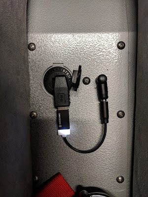
Turns out that the dust cover the Blue Sea socket comes with is too big to use (the F-01439 Seat Ramp Cover impedes its use).  So I just swapped dust covers with the Powerwerx socket.  Below the new socket shown with my Bluetooth audio receiver plugged in to it and the Music 2 In jack (I use 90 degree elbows to reduce the profile of the cables and thus reduce the chance of something breaking - that the particular USB elbow in the photo prevents the use of the other USB socket, so I later used a short 90 degree elbow USB extension cord).


 After adding it to my aircraft, I flew for a few hours without hash on the GTR-200.