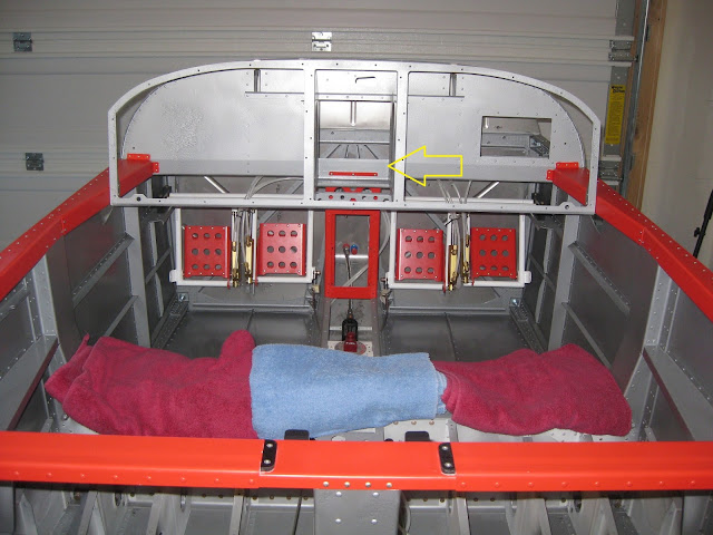
The F-01455 Sub Panel sits a little more than an inch above the F-140106 Wiring Channel, as shown below by the yellow arrow. The depth of nearly all of my Garmin center stack trays (the intercom being the exception) projects into this area.
So to accommodate the stack, I had to remove with a Dremel about an inch of the Sub Panel in that area.
However, even with the removal of that piece, the center stack still sits
higher than I had originally planned, so I had to redo my panel design
to accommodate this eventuality: The backup airspeed, altimeter (the upper right mounting hole of which will be unused, as it overlaps the F-01467 Instrument Panel Frame) and fuel gauges were moved to the right, whilst the ELT, Hobbs, AE Fuel Guardian and the defrost and avionics fan switches were moved to the center.
My RV-9A builder-friend match drilled the trays into position with a pneumatic angle drill.
A small slot had to be cut into each side of the F-01456-L/R Fwd Fuse Ribs to accommodate the wiring harness of the GTR-200. Not shown is some 1/8" aluminum angle that was match drilled into the Fwd Fuse Ribs for additional rigidity. I'm considering attaching the aft angles to the F-01467 Instrument Panel Frame too.
The EIS was located in the Sub Panel by cutting a rectangle out with a Dremel. Because the EFIS provides both the same and elaborated information, there is no need to see this instrument (though, in testing my wiring, it's apparent that the EFISs take some 30 seconds to boot, so one could argue that the EIS is still useful in a visible location).
The EIS will live here under the canopy, as shown in its matched-drilled location. Nutplates were added so the EIS can be removed without reaching behind the subpanel.
Update 2-Apr-16: I later used four pieces of 1/16" aluminum angle, 2 on each side, to reinforce where the trays screwed in to the ribs. The images below were taken on 1-Oct-16, after the panel was wired and installed.
The left image shows a piece of angle riveted to the F-01467 Instrument Panel Frame (this view is from forward of the panel looking aft). Notice that the angle has notches cutout in it to accommodate 2 of the 3 nutplates. The other nutplate was removed from the frame and instead attached to the angle. Furthermore, of the four screws anchoring the trays, the washers on the two middle screws were reshaped by grinding on the ScotchBrite wheel.
The right image shows a piece of angle with only two screws from the trays passing through it. This angle is not riveted to the airframe however it distributes the clamping force from the nuts over a larger area on the F-01456-L Forward Fuse Rib.


No comments:
Post a Comment