
I inquired about having the wiring professionally done and was quoted $3k-$5k. I deemed that entire range too expensive, so I opted to complete the wiring myself. Purchased tools were: Wire strippers, crimper and insertion/extraction tool.
GMA 240 replaced with a GMA 245 on 12-Aug-18.

Rather than make a classic wiring diagram, which I find difficult to read and remarkably unintuitive, I instead created in PowerPoint something I'll call a "wiring map" for each connector on each instrument. The objective was to track where each wire went to, make it visually appealing and very easy to read, especially when consulting the map to direct the fabrication of the harnesses.
Examples of these "wiring maps" are shown below. Unused pins are greyed-out. Colored rectangles for each position represent the instrument and its associated pin that each wire goes to. Circles represent the wire color used ("x" denotes the wire is placed, but the color is not recorded). ARINC, RS-232, audio and input/output allotments are recorded in tables.
Examples of these "wiring maps" are shown below. Unused pins are greyed-out. Colored rectangles for each position represent the instrument and its associated pin that each wire goes to. Circles represent the wire color used ("x" denotes the wire is placed, but the color is not recorded). ARINC, RS-232, audio and input/output allotments are recorded in tables.
GMA 240 replaced with a GMA 245 on 12-Aug-18.


As an example of the wiring: Left shows the GTN-650 P1001 harness. Right shows the populated pins for the GTN-650.


Completed GTN-650 harness.

For each wire's label, rather than buy an expensive heatshrink printer, I obtained various sizes of clear heatshrink (3/32", 1/8", 3/16", 1/4") and printed the wire function and pin number on slips of paper in 6 point font. A label was created for both ends of the wire (e.g., "7 RS-232 Out 2" on one side, "24 RS-232 In 2" on the other). A piece of heatshrink was slid onto the wire, with the label slipped beneath the heatshrink. A quick application of heat from my heat gun sealed the deal (literally). The credit for this approach goes to someone else and I happily stole it.
Some Garmin wires were pre-labeled and when appropriate, I used those and then discarded/re-purposed the others. Below shows the GTX-330ES harness with a few labels visible.

Here is what the spaghetti looked like when it was first connected on the "bench" (a.k.a., my kitchen table).

Powered up! After meticulously testing all inputs and outputs (via headset and multimeter) then configuring all devices' RS-232 and ARINC ports and verifying communications between units, it was confirmed that my wiring is correct. Amazingly, no fixes were necessary. The right EFIS is not shown in the picture below.
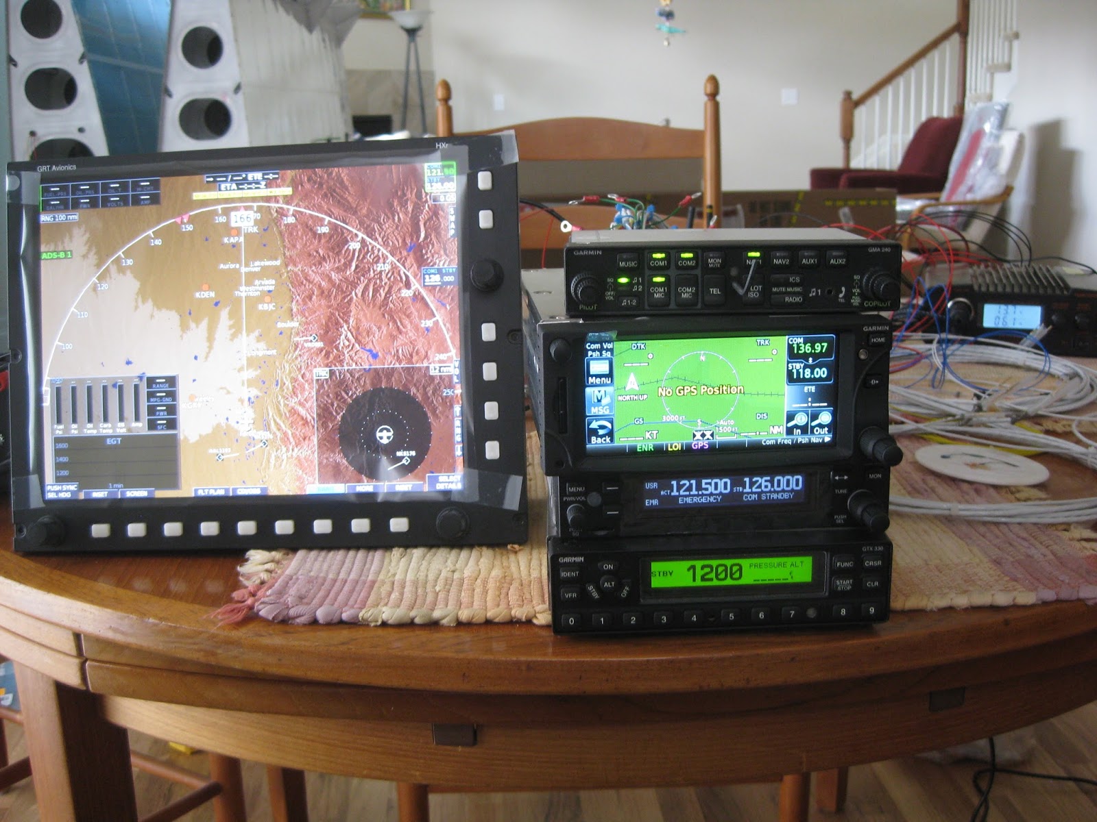
Update 5-Apr-16: I had to reclaim the space taken for the radio shop (a.k.a., the kitchen table) yet still wanted to play with my toys, so I setup the panel in a different room, connected antennas and the right EFIS. Now I can play pilot, listening to and seeing traffic and watching weather.

No comments:
Post a Comment