11 September 2013

Wings: Fuel tanks. Right tank capacitance probes and baffle install.

I decided to redo my fuel tanks.  See here for why.  The entries specific to the redone tanks are here.

For the installation of the capacitance probes, the RV-9 plans require you to cut a notch out of the vent line bushings to fit the wires.  Well, I had already installed the vent line, so that wasn't a viable option.  I didn't like the Van's method anyway since the wire could still fray up against the ribs with the notch removed.  Turns out there is a 7/16" hole at the top-aft of each rib which must serve the purpose of helping the fuel move around a bit or perhaps a tooling hole.  Since it's at the top of the tank, it wouldn't be a big deal to occlude it a skosh (effectively reducing its diameter) if I slipped in a bushing to carry the probe wires through.  So that's what I did, winding the wires around the vent line to help anchor them.


Capacitive probe on rib 6, inboard and outboard sides, prior to final sealing and tacking of wires.

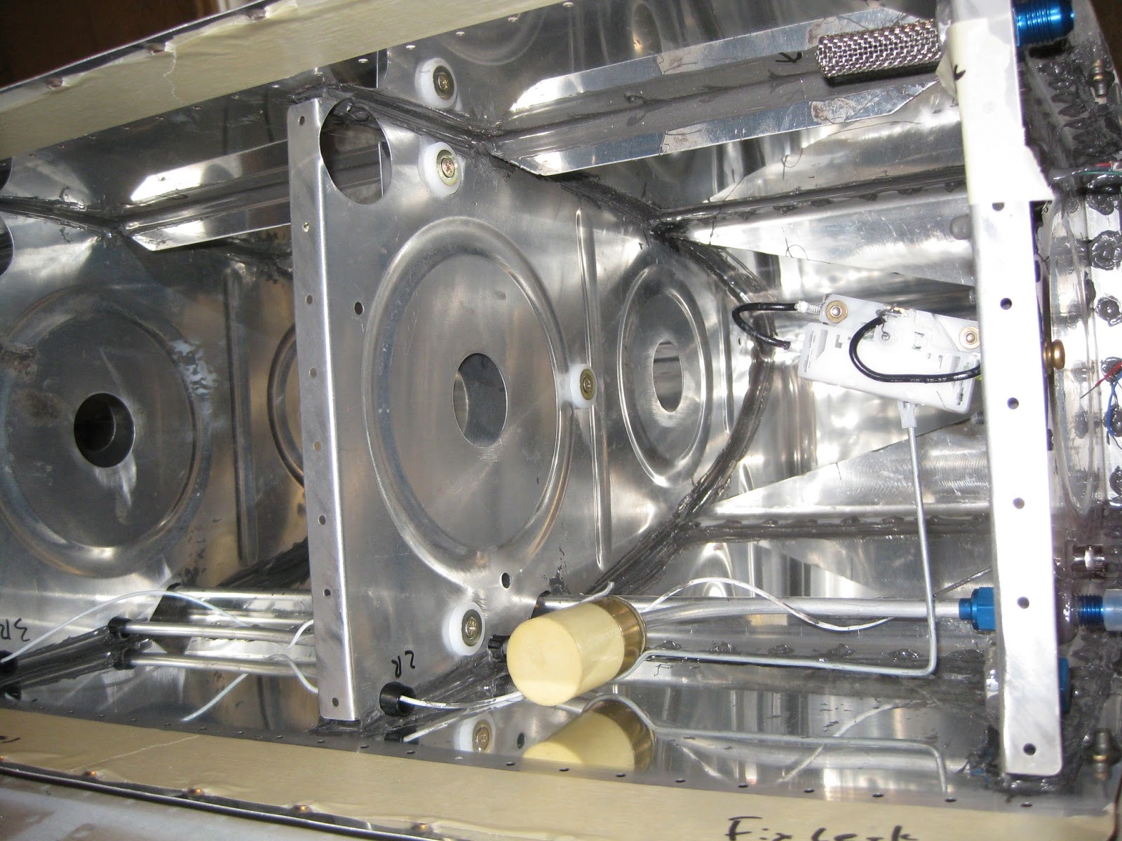
 

Capacitive probe on rib 2, inboard and outboard sides, prior to final sealing and tacking of wires.  Note the fuel float.  I will be using both means of fuel measuring (one for EFIS, one for steam).  Also the low fuel level optical sensor is visible.

For installing the baffle, since it needs to be sealed on the inside, the plans call for the following sealant methodology.


After dropping in the baffle, using a more liberal interpretation of the above, here's what the sealant looked like prior to the baffle install.  This was done with two stripes of sealant using the manual syringe gun.  For the left tank, I'll integrate some of Mouser's approach to mine.


And here's what the sealant looked like against the baffle inside the tank (the below image was taken through the fuel filler hole).  The sealant bead at the top is the baffle-skin joint (i.e., ignore the arrows).  I also put a very thin layer of sealant (thin enough to prevent skin pillowing) on the inside of the baffle flanges.


And here are the baffle and attach zees cleco'd.  I decided to sand down the primer I originally put on the tank attach zees' flanges so the sealant could get a better grasp of the parts.  May not matter, but surely won't hurt, especially considering how ridiculously tenacious that EkoPoxy/EkoPrime is!


Where the baffle webbing attaches to the ribs, all of the rivets are AH-41/2H blind, except the out- and inboard ones which are bucked AN470AD4.  The latter are very easy to buck solo, just be careful not to let the rivets work-harden prior to getting a good shop head.  Also, there is one AN470AD4-5 rivet on that outboard side that requires a deliberate approach since there is a AN470AD6-5 filling a tooling hole impeding good bucking bar access.

The tank will sit inverted for a week or so to promote better sealing against the baffle.  Probably won't make a difference, but it surely won't hurt.  Every rib and baffle rivet head (shop and factory) and all mating surfaces were slathered with sealant, including a fillet at all joints.


After a full cure, the last baffle rivets will be installed following skin countersinking.  Then it will be 1) final leak testing of left and right tanks, 2) priming of the baffle and outside rib faces then 3) hanging of the left and right tanks.

09 September 2013

Wings: Fuel tanks. Some fuel tank sealing and initial leak testing.

I decided to redo my fuel tanks.  See here for why.  The entries specific to the redone tanks are here.

Prior to the initial leak test, I went through the tanks with more sealant.  This encompassed slathering sealant under the curved surfaces of the J-stiffener and tank attach assembly brackets.  Because these areas are hidden from view, I used the "mirror-on-a-stick" approach to verify the slather. 
Update 17-May-14:  A much better way to approach this is described here.


The various fittings and the low fuel level optical sensors were installed and sealed.


The tanks were then dressed with toilet paper to preserve the evidence of any leaks (odd flashback of my youth notwithstanding).  With the tanks water-filled and a full tube of food coloring dye on board (not sure of the origin of this idea, but Mouser turned me on to it), they each sat for while soaking up life.

The right tank has three leaks:
  1. At the junction of the skin, tank attach assembly and inboard forward nose rib on the forward side.
  2. Filler cap left side at the cap's o-ring.
  3. Filler cap right side also at the cap's o-ring.
A liberal amount of sealant can fix the first one.  The last two will require some investigation.  They might actually be at the filler flange.  I would consider it a free vent, but I don't water to creep into the tank.  Incidentally, I tried with both the locking caps and the stock caps.  Both leaked (bot albeit, slightly different parts of the o-ring).


Right tank filled with water.  Leakage puddle visible on inboard side.  But no other rivet or seam leaks.


Internal bleeding?  No, just food coloring to stain the professional toilet paper detector.  Luckily the neighbors weren't curious about all the red water and associated stains on my clothes.


Left image:  Source of inboard leak.  Right image:  Two o-ring leaks on the cap.


The left tank has no apparent leaks.


No, not a fuel tank hematoma.  Just food coloring.

After fixing the leaks identified on the right and letting the tanks dry, it'll be time to install the capacitance probes and baffles, wait for curing and do the final leak test.

Wings/Lighting: Landing lights ordered.

Here are the posts pertaining to nav-strobe lights.
Go here to see the wiring of these lights into my airframe.

Decided to indeed go with a pair of the AveoMaxx Hercules 30.  Sure, they'll probably be cheaper later when I'm ready to fly, but they'll be easier to fit with the wing lacking the tips and bottom skins.  Incidentally, if you're considering these lights too, contact the company directly.  They may be able to get you a much better price than the distributors.  Shipped, the pair were $1,795.50.


AveoMaxx HERCULES H30
P/N: AVE-H30MWSSNH-00A

Technical Information
1. Number of LED: 30
2. Input voltage: +9..+36 VDC
3. Output power [Hi/Low]: 45/21W Taxi, 68/33W Landing, 113W/54W Taxi+Landing
4. Voltage protection: 80V, both polarities
5. Under-voltage lockout: 8.5V , not more
6. Over-voltage lockout: 37V, not less
7. Ambient temperature: -40C..+85C
8. Function description:
  • a. 1x12 LEDs - Taxi, steady light
  • b. 2x9 LEDs - Landing, steady light
  • c. 1x12 + 2x9 - Taxi+Landing
  • d. Synchro Mastrer function, active – low
  • e. Wig-Wag – Taxi LEDs only
  • f. Master/Slave select sequential and simultaneous Wig-Wag mode
  • g. High/Low power select for Landing and Taxi.
9. Beam Pattern:
  • a. 100 Vert 100 Horizont – Landing
  • b. 100 Vert 100 Horizont – Taxi
10. Light Intensity (calculated):
  • a. 104.000 cd - Landing Hi
  • b. 56.000 cd - Landing Lo
  • c. 62.000 cd - Taxi Hi
  • d. 32.000 cd - Taxi Lo
  • e. 166.000 cd - Landing + Taxi Hi
  • f. 88.000 cd - Landing + Taxi Lo
11. Color and shade: cool white, 5000K – White
12. Programmable Soft-Start, less than 50mS
13. Overheat protection, temperature dependent decrement intensity
14. Weight: less than 1.08lbs (490 g) with Aveo bracket
15. Useful life: not less than 30.000,0 aircraft flight hours.
16. Dimension: 4.33” Round x 1.79” (D = 110mm, H = 45.7mm).
17. Material:
  • a. Housing/Heatsink: Aluminum Alloy, natural anodizing
  • b. Lens: Clear Polycarbonate

08 September 2013

Wings: Pitot-static. Dual pitot plumbing completed.

I decided to go the dual pitot route, with the Dynon heated on the left and the normal Van's tubing on the right.  The Dynon will feed the EFIS and the "raw" tubing one will feed a steam gauge for backup.  Later, during panel design, I might even rig up a set of valves so I can choose and/or share pitots between instrument sets.  For this setup, I had to drill another set of holes in the ribs to carry the pitot lines.

Parts needed for for the Dynon:
Parts needed for both.
I had to add some holes in the ribs.  The right wing needed a set for the pitot and the left wing needed a set for the AOA (the plans included holes for the pitot line on the left).  Wish I had thought of this before assembly.  It was relatively easy to drill the 7/16" holes on the outboard ribs, but given the density of the doubler ribs on the inboard side, some headwork was required to work this out since the drill is far too large:  I used a 1/4" socket extension and inserted the unibit between each rib (since the unibit's largest diameter hole is 1/2", you can't pass it through each rib).


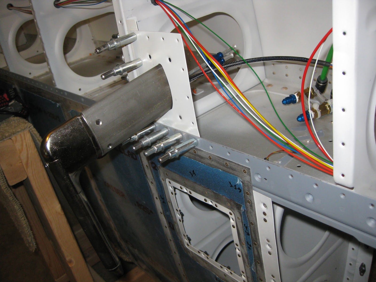
And left side first...I pulled the pitot and AOA lines through the left wing after installing the fittings with the spacer (thanks to Ken for the idea).  Then I lined up the Dynon tube to determine how much of the lines to cut with the pipe cutter.  After cutting to the right lengths, the nuts and sleeves were placed and the lines were flared with the flaring tool.  Here are a few pics showing temporary placement.  You'll notice I swapped the AOA and pitot tubing locations for better fitment.  The reason why I wanted the elbow fittings was to keep the lines coming from the Dynon tube straight so future servicing and/or removal should be easier (Update 9-Apr-17:  I ultimately routed the airs lines as shown here).


For the curious, the little gray spots on the spar webbing are areas that were scratched during leading edge installation that I later sanded out and primed.  Also, the red and white wires that seem to curl off to the right are the Dynon pitot heater and status light wires I strung earlier.  They're just pushed out of the way for now.  You can also see the extra wires I added for my landing lights.  More on that in a later post.

I also decided to countersink the PBK-12 Gretz Aero bracket after match-drilling and tapping the holes in the probe.  Because the bracket surface is curved, I c'sunk by hand with a deburring bit, very slowly.


Off to the right side...A 7/16" hole was needed for the right wing pitot (following removal of the rivet that was originally there).  The plans call for this to be done on the left wing, of course.  But that's where the Dynon heated pitot will be.  What's interesting is how little leading edge skin remains on the aft side after that hole is drilled.  Prior to mounting the hardware, this will need to be primed.


Here's the right pitot hung with and without the cover.  I used the kit's clear tubing for the right side pitot to help differentiate it later at the panel.


You can see some Cherry Max rivets in a bag that I'll be using on the right inboard leading edge rib.  Update 5-Dec-15:  I did not use the Cherries.  The difficulty I had with setting these AD470 rivets was that the offset rivet set kept spinning in the gun.  I've since learned to use duct tape to prevent the set from spinning and to increase the air pressure to accommodate the set's flexion.


Read the entries in my AOA series:

01 September 2013

Wings: Flaps. Ribs prepped and brackets countersunk.

Though progress on the previous sections continue, I'm waiting to post the associated updates until those sections are further along.  The flaps are among the several parallel workstreams I have going on right now.  Here's a few pics from the in-progress flap pursuit.

A collection of nose ribs in process and cradles setup with flap spars.  Cradle tip:  Use a longer piece of wood for the bases so your clamp doesn't impede flap fitment.


Left:  Ribs ready for tab removal, final-drilling whilst the hinges and doublers are ready for deburring.  Right:  Left flap cleco'd without skins and trailing edge.


The drill jig called out for in the plans to clear the hinge joggles.


Left flap structure with bottom skin.


Left flap cleco'd together.  The nose skin is held very tightly against the nose ribs.  This means that getting the holes to line up is quite a challenge.


I like flaps much better than the wing:  Small parts means I can work through them quicker.