13 January 2014

Shop: Belt sander purchased.

Picked up a Craftsman 21514 4"x36" belt sander today.  Will help me finish the lenses on the wing tips, the rudder stops and later Fiberglas pieces.


12 January 2014

Empennage: Aft fuselage. Bulkheads riveted.

Got all of the bulkheads riveted.  Mostly good work on my part, however I had two outcomes that will result in a lighter wallet.

First they get cleco'd up.

Then they get nailed together.

Horizontal stabilizer front attach bulkhead.   All rivets squeezed.  I actually had to remove and replace the two top rivets on the right attach bar.  On one I mangled the shop head by being off center with the squeezer and the other somehow got a rivet that was 1 mm too short.


Bulkhead with tail tiedown.  All rivets squeezed.  Notice the slight warping of the holes near the #12 screw holes in the bracket.  This was due to my dimpling those holes (per plans) only to realize that they should not be dimpled so I had to flatten them (plans need a revision on 10-07, step 1).  I also dimpled each hole in the web the wrong direction and had to re-dimple in the right direction.  Update 11-Dec-14:  I've decided to replace this bulkhead even though it's already riveted in.  Update 29-Jun-15:  The bulkhead was replaced after installation in the aft empennage.


Horizontal stabilizer rear attach bulkhead.  All rivets squeezed.


Aft bulkhead with rudder cable bracket.  I used the rivet gun to prevent warping such thin parts with the squeezer.


Forward bulkhead.  Again, I used the rivet gun to prevent warping such thin parts with the squeezer.


So now, the big mistakes.

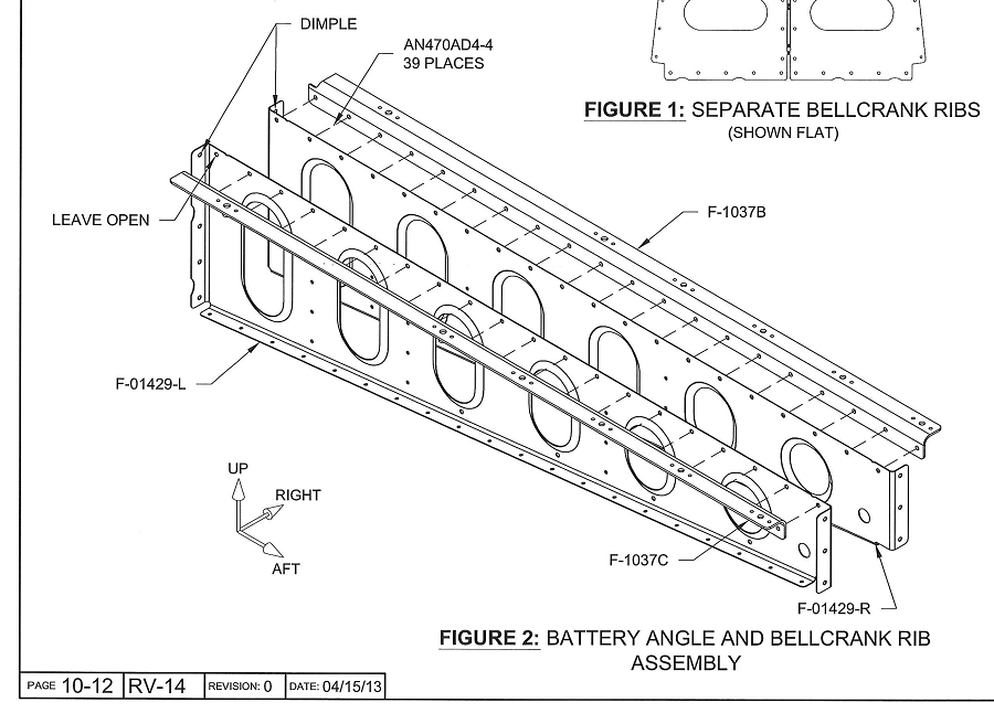
Mistake #1:  I took the picture on the left to be manifested in the physical world as on the right.  How could that happen?  See, I got overconfident on recently finding several rivet sizes in the plans that were inaccurate and decided the AN470AD4-4s called out should be -6s.  Proud of myself for finding another error in the plans, I later found that I was the one in error, but only after squeezing 19 rivets.


I decided I could drill out those 19 rivets to separate the parts and move on.  Which I did.  The holes were slightly enlarged, but not too badly.  However in the end, I decided that I didn't want that part in the plane with the stress introduced by my error.  So I'm going to replace those parts.  The battery angle is $17.  We'll see what the ribs are.  I'm awash in surplus nutplates so I don't need to purchase any more of those.  I'm actually solving two issues at once since I also had a countersink too deep on one of the battery angle nutplate attach rivets.


Also, the plans don't call for the bellcrank rib flanges to be dimpled #40.  They need to be as they will be directly riveted to the skin.

Mistake #2:  On the systems bulkhead, I dimpled not just the nutplate attach holes (the latter highlighted in red), but the screwholes too.  Not a big deal really.  I pressed them out, but because dimpling stretches the metal (especially for #8 screw holes), the part was no longer very planar.  Looking at it, I didn't want it in the plane, so I scrapped it and will replace it.  Also, whilst working on this bulkhead, I found out I was missing MS21055-L3 (a.k.a. K3000-3) nutplates.  Apparently, I'm not the only one.  Wasn't even on my manifest.

Empennage: Aft fuselage. Priming.

Nothing exciting other than priming a whole lotta parts.  For the first time, given the many parts, I used the dimpling table which is usually just out of the time lapse camera's range in the far field.  That table is shown in the bottom row, right side.


As an aside, I tried taking some pictures immediately after priming.  When the flash was engaged, the images came out foggy.  On cleaning the lens, they were still foggy.  I quickly realized it was due to the primer that precipitated out and became airborne.  I hadn't realized that this happened.  This is why I wear a respirator.  Left image, no flash.  Right, with flash.


The next day, I took a picture of all the parts that are primed and ready to go.  First we have what's in the basement...


...then for completeness, what we already have in the guest room.


I don't live in a house any longer.  It seems I'm living in a hangar that has no runway access.

07 January 2014

Wings/Lighting: Landing lights. Wiring complete.


Ridicuously bright.  The camera doesn't do it justice:  At midnight, this single light makes it noon.


The wing kit's harness wires are appropriately gauged for the currents they'll carry with the  AveoMaxx Hercules 30.  However, I needed to buy Tefzel wire for the three additional lines beyond the stock kit provisions. 

Here's the wiring of the lights with the wire colors from the wing I'm using overlaid.


Since the AveoMaxx Hercules needs 7 wires as I'm going to use them, the 9 position connectors below worked great.  Also, one of the lights has to be defined as the "slave" (otherwise wig wag would just be a wig and no wag), so I jumpered one wire from ground to the master/slave line.  This was done on the wing wiring side, thus the lights themselves get defined as master/slave by which wing they plug in to.  


All crimps were easily made with a budget crimper then soldered for security.


Here's the right wing connectors, not fully inserted.  You can see the ground jumper since I defined the right wing as the slave side.


Part numbers for the Molex connectors are:


I'll have to pull and reposition several pins on the wing root wiring harness.  For that one needs a Molex pin extractor (formerly Cat. No. 2062447).  I found mine on eBay and it works great.  I originally tried this extractor, but it only works for the male pins, despite manufacturer claims.


Finally, I need to work on the mount.  The mounts that came with my lights don't fit.  Looks like Van's kit isn't quite the PAR36 standard.  This image was taken looking in the landing light cutout directly towards the W-00017 mount.  Update 30-Apr-17:  I completed the landing light mounts.

05 January 2014

Empennage: Aft fuselage. Straightening horizontal stabilizer attach bars.

The horizontal stabilizer attach bars come with quite an inherent warp that needs to be straightened.  With similar parts in the past, I've simply clamped the parts in the vise and meticulously labored over bending it straight with elbow grease or made use of a hydraulic press.  Neither approach is a fun exercise as they take a lot of time.  The plans have an interesting approach too (the illustration itself is quite entertaining).


However, I recently ran into a different technique that was worth giving a try.  The idea is to use three dowels in the vise then placing the part to straighten in such a way as to "bend it out" straight.


The approach is quick and worked great.  The only two variables to concern oneself with is 1) how much force is necessary (too little and nothing changes, too much and you bend too far) and 2) how much space between subsequent bends.  It's important to have the part thoroughly deburred since it will be subjected to significant bending.  And the use of eye protection and ear protection would be wise, should the forces at play overcome any of the approach's constituents.

Here's a comparison of the results on a flat steel plate (the underside of my back rivet plate).  The top bar is as received from the kit.  The bottom bar, initially curled by the same amount, as straightened using the above technique.