30 November 2013

Wings: Aileron actuation. Complete.

Aileron actuation is complete.  The rigging took me 11 hours.  Most of that was consumed in using the wrenches in the severely restricted space within the wings.

First, one of the threads on my pushrod threaded rod end was damaged. Don't know if it came like that from the kit or if the weld shop did that (probably the latter, as it looks like drop damage).  Fearing $100 to fix (new rod and welding labor), I learned I could use a rethreading die to solve my woes.  This is part of the "education" mandate in experimental aircraft construction.  I.e., I did not know one could fix damaged threads.  Below is the 1/4" 28 TPI die itself and in action.  I used a little oil to help it cut, along with a progression of two twists forward and one or so back to remove the debris.


Left side is damaged thread, right side is fixed.  The thread was bad enough to strip the AN316-4R jam nut.  I had to replace it.


The plans call for a 1 1/64" spacer to be used to clock the torque tube subassemblies. 


That's some mighty fine resolution in measurement.  I whipped out my compound miter saw to cut a piece of wood down to about 1 1/8" then worked it down with a long, flat file using my caliper to measure.  Once that was done, it's just a matter of engaging the torque tube collar to the right length (I went for 17 3/4") then completing the requisite match drilling.  Left and right shown on their respective sides below.


I foolishly torqued in the final bolts before approaching the wing roots.  Realizing I skipped a step, I eviscerated some time removing a few bolts.  Curious why my collars are primed grey and not the usual white as seen elsewhere in my build?  Read here.


Installation of the subassemblies must be completed with little to no pre-loading on the flanged bearings.  On each side, I had to use three NAS1149F0432 washers (two on top, one on bottom) to properly seat the subassemblies. Left and right shown on their respective sides below, top to bottom.  The washers are clearly visible.


Here they are, torqued down awaiting Torque Seal and the next pushrod.


The plans call for a NAS1149F0363P washer to be inside the torque tube clevis arm along with the pushrod bearing.  This is not easy as the arm must be spread to fit the bearing and washer.  I wonder why Van's called for this.  Left on left, right on right.


Here's the bellcrank jig to hold the assembly in the neutral position.  This is to properly size (by engagement of the rod end bearings) the torque tube to bellcrank pushrod.


Aileron pushrod installed onto aileron.


The alignment template holds the aileron in the neutral position.  Notice how the aileron is actually deflected slightly upwards.  This is apparently by design


Everyone's torqued down onto the left bellcrank.


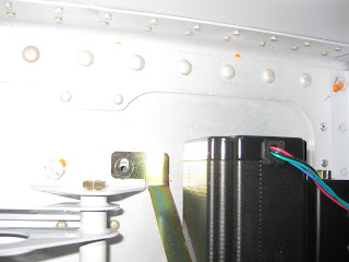
The torque tube gets very close to the main spar web in the full up position.  That might require sanding out later (Update 15-May-18:  It didn't).  The hole that's shaped in the kit seems to be too large inboard and too small outboard.  It almost as if the hole should be translated outboard in the master plans.


Wing tips next.  I marvel at the folks who bang out wing kits in 300 hours.  I'm on track for 600+ (Update 15-May-18:  It took 611 total)!  On 21-Jul-13 I guessed 450 hours when the tank baffles were ready for countersking.  On 5-Oct-13 I guessed 700 hours when the flap skins were being bucked.

28 November 2013

Empennage: Kit finished...Well, not mine though.

One of my fellow builders in the area completed his empennage kit in less than 30 days.  He's a machine and probably the first builder to complete the tail (and wings too!).  The fiberglass tips are missing in the picture as they were off awaiting finishing.  The lower rudder fiberglass cover is off awaiting a wiring diagram.  25 days into my empennage saw me get as far as completing the inventory!


Here're his wings, just to complete the picture.  He finished these in seven weeks.  Seven weeks into my wings had me still riveting the rear spar on!


See his later fuselage in-progress and his completed finish kit.

Wings: Right aileron mounted.

And now the right aileron is mounted.  Those MS21042-3 locknuts provide some serious friction!


Both wings with their ailerons.  I need to pull the left wing's carpet higher.


27 November 2013

Wings: Bottom skins. Right outboard skin on.

The right outboard bottom skin is on the wing for good.  Both bottom skins on the right wing were riveted solo.  Generally, this wing went much faster than the left side as that previous experience (literally) carried over.  Instead of placing one rivet-at-time, I would tape in a rivet per rib then bang them in across the wing, moving down to the next row (columns would be ribs).  For the J-stiffener and spar flange, I went outboard-to-inboard 5-to-6 rivets at-a-time, each bolus taped in.  Made things much faster.

Below is when the aft half was complete.  The blanket in the background was for my poor, poor knees.


I had some consistent trouble along the 11th rib on the forward half.  The bucking bar slipped off the rivet at four consecutive locations, giving the skin a good bit of...character.  Otherwise, there are far fewer dents than on the left and only two Rivets of Shame were needed.  And no oil-canning as I was fastidious about the riveting order.  A different outcome than the left side.


This also marks the end of use of AN426AD3-3.5 rivets for the wings.  In fact, this marks the end of all bucked rivets for this kit, given where I'm at.  This bottle, back in April, was nearly full!

24 November 2013

Autopilot: Roll servo fitted.

I've decided to go with the Grand Rapids Technologies suite of instruments for a variety of reasons.  This means that some (much?) of the preset wiring for the kit will be discarded as they're for Dynon (Update 19-Apr-17:  I ended up doing all over the wiring myself).  The first departure was the autopilot roll servo.  Don't need the kit's wiring for that.  In speaking with GRT, it seems I'm the first RV-14 installer of their servo.  Since the -14 wing is just a shortened -10 wing, GRT suggested I use their high-torque roll servo kit.

Van's provides a servo mount for the -14 which includes an aperture on the outboard side to accommodate a Molex socket that isn't needed for the GRT harness.


GRT's RV-10 mount is, other than that aperture, the same as the -14 kit's mount.  Turns out that aperture does not impede the servo arm's travel or its AN3H-7A bolt.  So there's no need to use the bracket from GRT's kit.

GRT doesn't have an install manual (though they are working on one).  They told me that their servos are physically identical to Dynon's and TruTrak's so I used their install manuals to figure it out (Brian has a nice set of images documenting his RV-10 install).  However, the servos from each of the three manufacturers are not identical.  This is a key point when it comes to the support bracket, as described later.

Here are some images showing a pre-install test fit.  Below you can see the white (primed) bracket that comes with the -14 kit.  The black bracket is the one for the -10 included in GRT's kit.  Other than the aperture, they are the same.  Again, it's clear that the servo's arm will clear the aperture on the stock bracket.


Here you can see how the servo will sit in the bay for the aileron bellcrank.


However, because of the weight of the servo, there is a support bracket that braces the servo against the upper bellcrank bracket (see below, from Dynon's manual).


GRT includes some stock metal in the shape of an "L" and leaves it to the builder to shape and drill.  I deemed it too difficult for my skillset as I was unsure how to get the bends at the correct angles and lengths so the bracket would fit properly.  Given that GRT told me that their servo was the same physical size as the others (again, they're close, but not quite the same, as I learned), I bought Dynon's support bracket. However it was both too short and that screw with the safety wire (henceforth, SWS) prevented it from fitting.  The SWS of concern is shown below.   It's the one at the top (which is forward when mounted in the airplane).


Next I bought TruTrak's bracket to see if theirs would better fit GRT's servo. All brackets are shown below (GRT, TT and Dynon support brackets left-to-right) after I modified TT's and Dynon's (described in next paragraph).  Also, both TT's and Dynon's brackets are much more rigid than GRT's.  The former are cadmium-plated steel.


TruTrak's bracket was slightly longer but it too would not accommodate the servo's SWS.  So, I bought a 9910 tungsten carbide cutter for my Dremel and enlarged the hole so the SWS would fit (I did the same for the Dynon bracket, as shown above, just to see if fitting would improve).  Following that, I then found that the AN960-10 washer would not clear the SWS, as shown below.


Thus, I ground down the AN960-10 washer on the Scotch-Brite wheel to clear the SWS


With the TT bracket secured to the servo body, it was clear that the foot of the bracket was not aligned with the hole for the upper bellcrank bracket when the servo body was secured to the lower bellcrank bracket.


However, after pushing the servo body down with some slight deflection of the lower bellcrank bracket, the servo can be mounted securely.


The RV-14 plans call for a nutplate to be attached to the right bellcrank for a roll servo (below from page 23-05, 15-Apr-13 revision).  It appears the other models require a bolt with a nut.  Van's just made it a little easier with the -14.

Below shows the tight clearance between the bellcrank rod end and its AN970-3 washer even when using two AN960-10 washers in addition to the 0.563” aluminum spacer. It appears that three AN960-10 washers are needed for proper clearance.  Clearly the spacer needs to be about 0.12" longer.


So, as of now it fits.  But I plan to coordinate with GRT to see if they'll release a spacer and support bracket specific to the -14 (Update mid 2018:  They haven't).

23 November 2013

Wings: Aileron actuation. Bellcrank to aileron pushrods.

Since the torque tube to bellcrank pushrods are aluminum, they could be primed with my usual Stuart System's EkoPrime (reminder, don't use a water-based primer on steel).  For the interiors, I taped off one end of the tubes and all the rivet holes then poured the primer down the tube.  After rolling it around for a while, it was well coated.  Curing took more than a week given the absence of airflow and puddling on the bottom of the tube (every day I'd rotate it 90 degrees to spread it around a bit and mitigate puddling).  This is a key point since the VA-111 Threaded Rod Ends were previously sanded to fit snugly without primer, so a puddle of dried primer on the interior just makes fitting that much harder.

Here's the VA-111 Threaded Rod end prior to riveting.  I took this picture to match the image in the plans.  I used Napa 7220 on the rod ends since it's thinner and more compliant when sprayed on threads (Stuart's can gum up threads).


Given all the primer in the tube's interior, it wasn't an easy task to get the VA-111 threaded rod end in there.  I had to pound it in against my workbench fairly violently.


It's key that the holes are well aligned prior to the pounding, otherwise you're left with trying to rotate a piece trapped by a lot of friction.  This happened to me on one end so I had to use the approach shown below to rotate the piece.


Here are the completed ends.  The MSP-42 rivet manufactured heads conform to the tubes' curvature - not something I expected to happen.  Rod ends need a quick touch-up of primer before final install.

Wings: Aileron actuation. Bellcrank to aileron pushrod weld.

Turns out that not only is it difficult to drill steel, as I learned with the aileron counterweights, but it's also difficult to drill into steel straight, from one end of a tube to the other.  In fact, I totally botched the first pair of steel pushrods and had to drop some $30 for a replacement tube (ST4130-035X1/2X48-PC).  To make things easier, one ought to use a drill jig (my approach) or use Mike Bullock's miserly approach.  In either case, the jig helps secure the tube in the drill press.


However, after drilling my steel pushrods, I came across the notion of welding the bushings into the pushrods rather than riveting.  This notion is fraught with some interesting discussion with respect to the hardness of the steel following the welding.  It appears to essentially come down to, yes the steel will be weakened, but it will be far stronger than 2 rivets holding each bushing in.  Also, the use of aluminum rivets on steel can promote corrosion due to the dissimilar metals.  Apparently, this approach is not permitted in the certified world.

Ultimately, I decided to have a local shop TIG weld my bushings for fifty bones.  You can see the holes I previously drilled for the rivets.


And I reprimed the areas where the powder coating was removed.  The interiors were primed (not shown) by taping off one and spraying Napa 7220 (reminder, don't use a water-based primer on steel) in the tube and rolling it around until the interior was covered. 


I decided to drive rivets into the bushings anyway, as an extra measure of safety, should the welds break.  Though ideally I would use MS20615-4M11 (which I can't seem to source), the concern of any associated corrosion is fairly minimal given the thousands of kit planes in the air using that approach.  With that in mind, I went with the plans' recommendation of AN470AD4-11.  Not the prettiest shop heads in the world but they'll work fine if the welds break.  I drenched the area with primer to mitigate corrosion.