30 June 2014

Wings: Fuel tanks redo. Primed their exteriors.

Because I'm redoing my fuel tanks, I'm really only posting progress reports rather than additional details.  See here for why I'm redoing my tanks.  Technique details on the original fuel tanks are found in their associated posts.
Why not prime the exteriors of the tanks once verified as non-leaking?  And who cares if the primer makes a mess because the spray volume wasn't properly adjusted?


29 June 2014

Wings: Wing tips. Tip ribs match drilled.

The key to getting the tip ribs in the right place is to make sure they are placed in such a location as to be aligned with both the ailerons neutral and the flaps up.  That takes a lot of back-and-forth to finally set.


Then match drill the aft few holes after marking off their proper locations.  This locks the rib into place.


Then pull the tip off and complete the remaining holes per proper spacing.


Following this, the holes in the tip get countersunk and the rib gets riveted in.  I'm holding off on the last step because my wing tips are too long by nearly 1/4".  I'd rather work on the fiberglass without the ribs in place.

Wings: Pitot static. Mast powder coated.

Nothing too exciting here.  My -9A friend graciously had my pitot mast powder coated.  Decided to go with a silver that matches the pitot tube well enough.  That should then match whatever color the plane gets painted.


Read the entries in my AOA series:

28 June 2014

Wings: Fuel tanks redo. Leak testing complete.

Because I'm redoing my fuel tanks, I'm really only posting progress reports rather than additional details.  See here for why I'm redoing my tanks.  Technique details on the original fuel tanks are found in their associated posts.
Both fuel tanks don't leak.  Mostly.  The right tank had a small leak at the ground screw on the sender.  The left tank had the same leak plus another on an adjacent screw.  I fixed the leak on the adjacent screw with some Loctite (removed screw, dressed threads, rescrewed).  I'll do the same on the ground screws once the tank is mounted and connected to the wires.  I'll probably dress each screw with some sealant where it contacts the sender plate, just to be safe.

Here is testing in progress.  Used a cup of very soapy water and a brush to "paint" the soap on every rivet and seam looking for bubbles.


Here's one of the leaky screws on the left tank.


No leaks on the right baffle.


And here's a little tip that's great.  Out-of-the-box, the fuel caps don't make a good seal with the fuel flanges.  On my first tanks, I simply duct-taped the heck out of the area to keep the tank pressurized whilst I checked elsewhere for leaks.  However, there is a small nut on the underside of the cap.  You turn that nut to control the tigthness of the seal.  Each of my caps needed about a full turn.  No leaks!  Many thanks to my blog reader Ken for giving me this tip!


Still using my locking caps.

22 June 2014

Wings: Fuel tanks redo. Baffles sealed.

Because I'm redoing my fuel tanks, I'm really only posting progress reports rather than additional details.  See here for why I'm redoing my tanks.  Technique details on the original fuel tanks are found in their associated posts.
On these tanks, I decided to dimple the skins and baffles rather than countersink despite the plans suggesting the latter (here is one reason why the plans state to countersink). Turns out, the dimpled baffle slid right in without issue.  I didn't have to pull the skins apart at all.  The bead sits nicely against the holes as seen on the left tank on the outboard edge.  Compare with the (very generous) bead on my original tanks, which have countersunk holes.  How did I get such a beautiful bead on these tanks, as shown below?  Read here.


A peek inside the fuel flanges of the left (top) and right (bottom) tanks.  You can see on the right tank, I had included two beads on the outboard rib, #7 (bottom left image).  The second bead was ultimately superfluous.  In each image, up is looking aft (to the baffle web).  So on the right tank, left is outboard and on the left tank, right is outboard.  On the sixth rib of each tank, you can see one of the screws with a Tinnerman washer and spacer holding the respective capacitive plate.


And no need to shave down the prideful rivets due to poorly cut countersinks, as I did in my original tanks!  All baffle rivets are nice and flush.  Below is the right tank's baffle rivets.  Left is outboard top, right is inboard bottom.


14 June 2014

Wings: Fuel tanks redo. Capacitive plates installed. Tanks passed water test.

Because I'm redoing my fuel tanks, I'm really only posting progress reports rather than additional details.  See here for why I'm redoing my tanks.  Technique details on the original fuel tanks are found in their associated posts.

Capacitive plates installed (see here for how these were fabricated on the original tanks).  I feel like I did a much better job than on my first tanks.  Right tanks on top.  Left tanks on bottom.  Just need to tack seal a couple of places along the wires before I call this "done".


Tanks passed the water leak test, save for some leakage around the float sender's hex screws for both tanks, which is an easy fix.  I took the same approach as I did for the first tanks, just no food coloring or toilet paper.

13 June 2014

Empennage: Elevators. Bucking final rear spar rivets solo.

For all of the rear spar rivets that needed to be bucked, on both the left and right elevators I had help, which made the process much easier.  The plans have you hold off riveting a few of the bottom skin-to-rear spar rivets so that there is better access for sealing in the trailing edge foam ribs.  I didn't have help for those remaining rivets, so I needed to come up with a way to hit them myself.  The challenge being, as I had previously learned, keeping the special bucking bar from slipping off the rivet during bucking.


Here's what I came up with.  Propping up the elevator with shims to prevent deforming skins as per plans, I locked the elevator in place with wood blocks clamped to the table against the tip rib assembly and horn then sandwiched the bucking bar in place with clamped wood blocks too.  I would move the clamps and bucking bar as I progressed through the remaining rear spar rivets.


You can see my left hand pushing down on the bucking bar, with the steel plate underneath it acting as a fulcrum, so that the bucking bar pushing up against the shop head of the rivet.


Hitting the inboard-most rivet was a bit of a challenge with that root rib coming in at an angle.

08 June 2014

Empennage: Elevators. Horn fitting to right spar.

I had the pleasure of building three right elevator spars before I finally was happy with what I had.  

Spar #1 was messed up due to builder error:  I didn't like how two tip assembly rib-to-spar AD4 rivets were sitting.  When I went to remove them, I completely botched the procedure (it's tight quarters in there) and the replacement rivets looked horrible (in fact, one went to an AD5).  I deemed them unacceptable (see below), though two tech counselors disagreed with me.  So I scrapped the whole spar assembly (spar, tip rib assembly, root rib and horn) in favor of a new one.
 
Update 19-Sep-20:  On having the opportunity of building another elevator, it occurred to me that it may be better to not follow the plans' order of riveting.  Thus, on page 09-16, I prefer replacing Step 2 with riveting the E-904 Tip Ribs to the E-00902-1L/R spars first, the riveting the E-903 Tip Ribs to E-904 and E-00902-1L/R.  This allows for easy squeezer access to those rivets shown below.


Spars 2 and 3 related to the horn fitment.


Spar #2 went along just fine in the beginning.  The tip rib assembly was a real pain to line up with the spar, but I managed to do it after several hours of frustration.  The horn was easily final drilled to the spar and root rib.  Then the root rib was riveted to the spar.  But, when I went to rivet the spar and root rib to the horn, the holes no longer lined up between the spar and horn!  After spending a few hours trying to solve the problem, finding myself perplexed, I chalked it up to builder error and scrapped the whole spar assembly in favor of a third attempt.  However, to see how the spar-horn holes would look, I final drilled the horn to the spar and root rib.  The spar-horn holes were horribly oblong, as expected, and shown below (in executing the final drilling step, I now of course had #30 holes in the horn).


Spar #3 reused the horn from the second spar.  This meant the horn had #30 holes in it and the spar and root ribs still had the corresponding #40 holes.  For this third attempt I took a different approach.  I figured if I riveted the root rib to the spar, then final drilled the horn to the spar and root rib when cleco'd to the elevator skins, I could avoid any misalignment problems.  See, because the root rib is flush riveted to the spar, in the plans riveting the rib to the spar is saved for after the horn is final drilled.  So in my mind, there could be some lateral movement freedom of the root rib that wouldn't be present otherwise.  Turns out, even after this sequence modification, I still had the same issue, as seen below.  (The image below shows some trouble I had priming the third spar:  My HVLP gun was not setup right so it was spitting out too much primer.)


At this point, I was skeptical of the problem being builder error as I had no such issues with the left elevator and the first right spar and I didn't believe I was doing anything different.  So I took a closer look at the three right spar assemblies I now had to see what differences I could find.  See the images below.


So clearly, the right root rib from my second (not shown) and third spars were misshaped.  On the second spar assembly, the problem manifested after the final drilling of the horn one doesn't rivet the root rib to the spar until after final drilling the horn to the assemblies.  So, the root rib's movement isn't restricted at this point.  

Upon consultation with Van's, they suggested I could bend the root rib to make it fit.  However, I don't believe they fully understood my findings.  Whatever machine is used to make that curve in the rib didn't put the curve in the right place.  It's as though the rib wasn't fully inserted (or inserted too far) into the bending machine so the curve happened slightly offset from where it was supposed to be.  Unfortunately, it isn't something that can simply be adjusted with a bend (or if it is, the method for doing so escapes me).  That bend has to be "rolled out" (sort of like what one does with a tape measure when you push the tape down on a surface). 

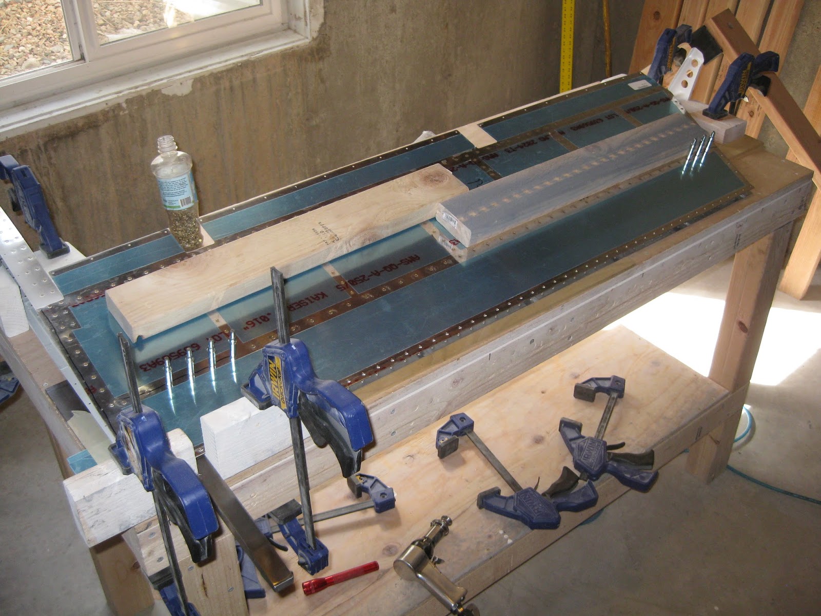
To make it work, what I did was cleco the horn to only the root rib so the horn was free to move along the spar (as free as it could given that the rib curve was restricting it).  Then I pushed, really, really, really, really hard on the horn so I could manage to sneak in one silver cleco.  Then I used my punch to wiggle the horn closer to a better alignment with the holes. I managed to get all six clecos in, very tightly.  However, I felt like the parts were under a lot of stress, so I didn't want to end up locking in that stress when riveting together.  So I took the horn off in favor of a different approach.
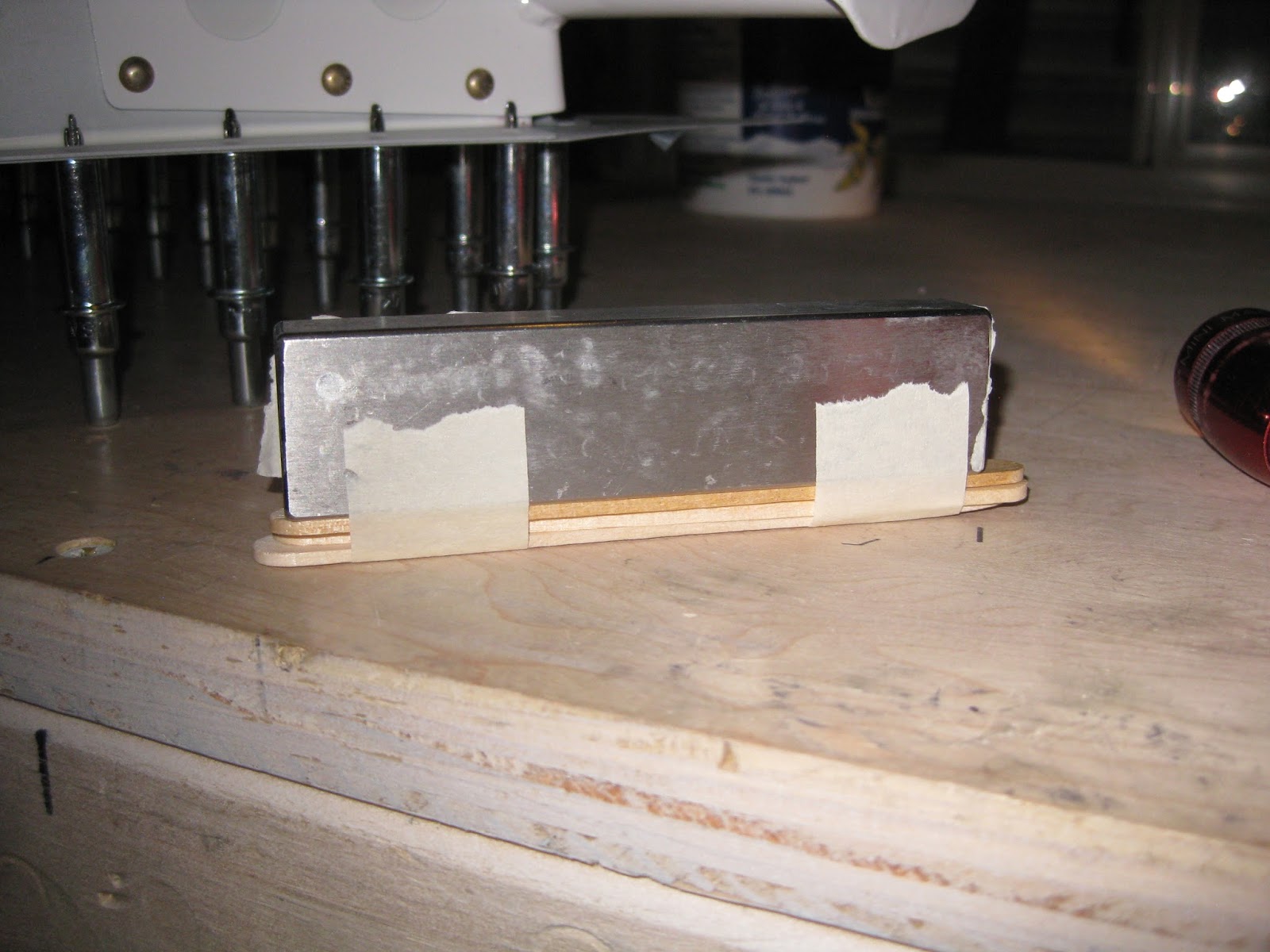

On the root rib I pushed really, really, really, really hard with strategically placed wood blocks to try to change the curvature of the root rib.  Seeming like I might have, I put the horn back on and using the same method as before, I convinced myself that the parts weren't under stress (or at least, not as much as before).  Now, keep in mind I'm reusing a horn that already has #30 holes in it.  So I had to make sure that the #30 holes I was 
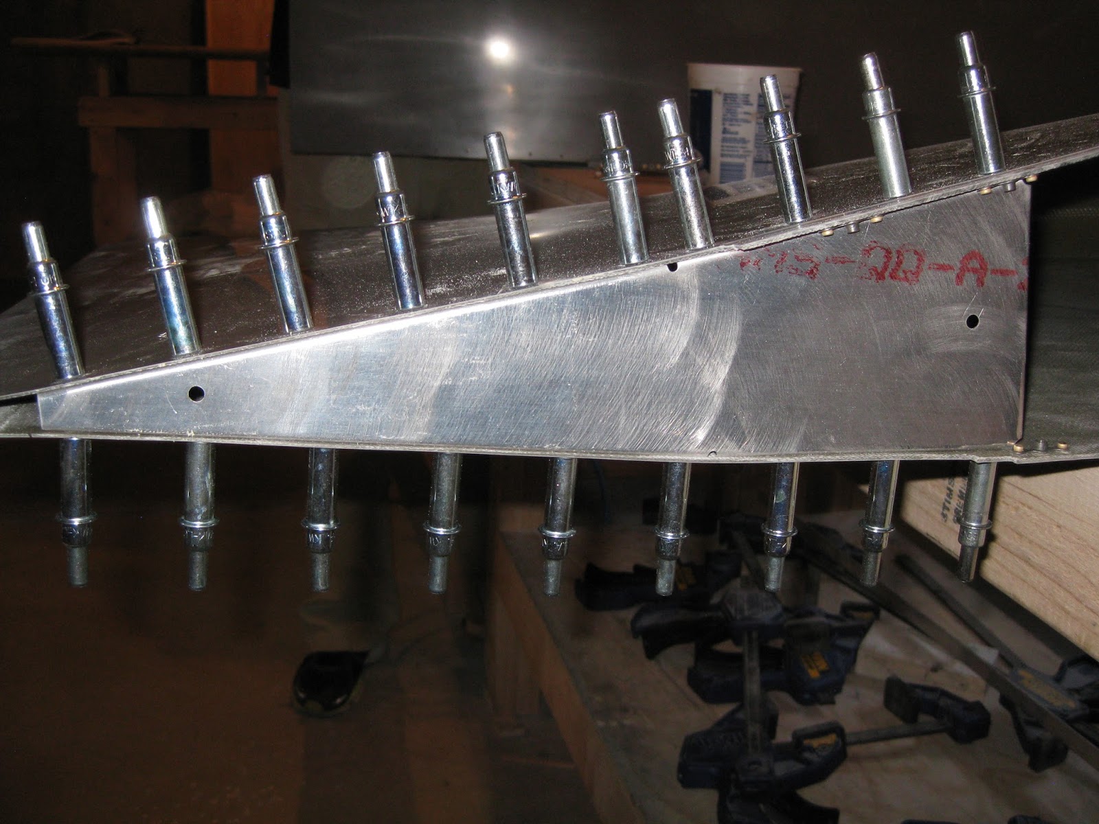
going to drill into the spar would be round as the spar had #40 holes.  To do that, I had to ensure that the #40 holes in the spar would at least be tangential to the #30 holes in the horn (i.e., prior to final drilling, the holes should look like what's on the left rather than the right).  Using my #40 punch, I visually confirmed this desired outcome on all 12 holes.

When I final drilled the parts, I did not remove the entire set of clecos to debur, rather I removed one at-a-time to debur.  This way I ensured I wouldn't lose alignment like what might have happened on the second spar.  Every hole was round and each rivet slid in to its hole without resistance and not at an angle.  After riveting, the horn sits nice and flush on both the 
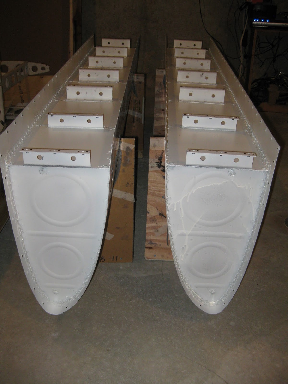
rib and the spar.  So, long story short, I now have this wonderful sight 5 months after messing up the first spar.


Which is now ready for the trailing edge and foam ribs.


I hope this explanation made sense.  For a problem that is essentially simple, it is surprisingly difficult to articulate it with a reasonable level of clarity.

Empennage: Elevators. Riveting the gussets.

It's a bit difficult to access the inboard gusset on the elevators.  You have to lift the skin up (assuming you remembered to exclude the associated skin rivets earlier on 9-18) to present yourself with a restricted workspace to slide in a bucking bar.  This is not a place you want to make a mistake (smile, bucking bar slip, etc.) as rivet removal would be a challenge.  For example, I ended up with an AD4 on the left elevator.


First thing to do is place some masking tape on the manufactured heads of the rivets to mitigate the rivet set from slipping and imposing a big toothy smile in the head.  Next, use a bucking bar that is appropriately dimensioned for the task.  I used Mr. T. as, when laid on one side, it lines up well with the lower gusset rivet.  Then, to hit the upper rivet, I taped some Popsicle sticks to the bar so it was elevated enough to cover a well-formed shop head.


Here's what the inboard gusset looked like after bucking.  Not too bad.


A similar exercise is done with the outboard shear clip.  The trailing edge rivet has a slightly angled shop head, but entirely acceptable.