31 December 2013

Empennage: Elevators. Right elevator parts primed.

With the weather turning to snow tomorrow and the realization that I misaligned the piano hinge on the trim tab during match drilling, it wasn't reasonable to get the left elevator ready for priming today (I do the cleaning and etching outside).  Turns out that was a good decision anyway since there were so many parts between the two elevator halves, that priming each separately is more manageable.  So after a whole lot of deburring and dimpling, it was off to priming.

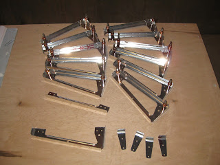
First the skins.  Yes, those are all of the right elevator parts sans the trailing edge, 2 hinge reinforcement places, fairing, foam ribs and horns!


Then everybody else.


I actually have not yet put an edge break into the skin trailing edges nor have I dimpled them yet.  I need to get an "economy" dimple die set set so I can modify it to avoid overlapping the bend in the skins, as called out for in the plans.  As an aside, edge breaks on trailing edges are very important..

30 December 2013

Empennage: Elevators. Temporary assembly and match drilling.

The right elevator has been temporary assembled and all trimming and match drilling is complete.  The left elevator is nearly at the same point.  The steps here aren't dramatic and are fairly routine.  So this is just a chronicle of the busywork necessary to trudge through the process.

First, a lot of ribs need to be cut then cleco'd.


Then the tip rib assemblies are put together for match drilling.  These attach quite tightly, so match drilling is important.


The elevator trim tab close-out tabs need to be cut.  These are the tabs that will serve much like a lateral rib to fair the air at the gap between the elevator and the trim tab.  After marking the cut lines (left), the cuts came out nicely (right).


Next, the left elevator's skins need their close-out tabs bent properly.  After aligning them on the "bend jig" (left), the bend is completed with a wood block, then a few light taps with the mushroom set on the rivet gun and finally followed by the hand seamer.


Here is an edge-on view of one of the tabs following bending.  Not perfect, but not bad at all.


The bottom skin goes on with the tip rib assembly (left), then the top skin goes on (right) with the newly trimmed trailing edge and horn.  These pictures are the right elevator.


For the left elevator, since it includes the trim tab, the piano hinge gets cut and match-drilled.  First to the elevator rear spar (left) and then to the trim tab spar (right).  I cleco'd and clamped the heck out of it to make sure it was good and straight as I went along.  *Note, for the trim tab, I put the piano hinge on the wrong spar flange so I need to scrap that half of the hinge and redo.  Thus, the right picture is in error and should not be duplicated.  Do not use the flange with two holes.  Use the other one.


Here is the temporarily held together right elevator.

Empennage: Rudder. Counterbalance rib riveted to spar.

I decided to redo my rudder due to the trailing edge.  Here is the post outlining the new rudder.

I wouldn't normally post for such a mundane task, however I wanted to document my approach here.

Squeezing rivets sometimes causes thin parts to distort, especially rib flanges.  Since this rib will be holding up a hefty bit of mass, best to keep the flange as flush against the spar as possible.  So for the rudder counterbalance rib, I wanted to buck the two AN470AD4-4 rivets with their manufactured heads on the forward side. 

Bucking the rivets would require an offset rivet set.  With the requisite higher air pressure and spinning rivet set, I wanted two hands on the gun.  So I propped the bottom side of the rudder spar up with wood blocks.  The top side of the spar, with the shop head(s) protruding, was rested against my dumbbell bucking bar with a steel plate under it (the latter mitigates the dampening of the gun blows by the wood).  In no time, I had two great shop heads and a nice flush rib flange.

28 December 2013

Empennage: Horizontal stabilizer. Spar doublers and brackets riveted.

Both horizontal spars are ready for ribs.  The aft spar has brackets (left) in addition to the doubler (center and right).  I'm showing both sides of the riveted doubler below.


The forward spar includes the spar caps.  I cleco'd the heck out of those when riveting to make sure they fit good and tight.


I did make a mistake and riveted in a universal head where a flush head rivet was called for.  Removing that was interesting since that countersink could cause trouble.  So I used my pin punch to start the hole, then drilled down flush to the spar with the following sequence of bits:  1/8", #42, #40, #36, #33 and #30.  I took that cautious approach to be sure my hole was centered.  When I popped off the manufactured head, I was greeted with a perfect sight (left).  I wacked the shank a few times with my 1/8" pin punch and the thing wasn't coming out.  I figured, since there were three thick parts being held together, the shank may have a non-uniform diameter.  So I decided to snap off the shop head too, using the same sequence of drill bits as before.  That was the first time I've removed a shop head.  Nothing to it.  Turns out, still couldn't get that shank out.  So I started drilling out the shank's center to relieve the pressure.  It took up to a #33 followed by the punch to get it out.  Notice the shank's non-uniform diameter (right).  This is why it was so hard to get out!


Forward spar with its caps and doubler, both sides.


Empennage: Rudder. Spar riveted.

I decided to redo my rudder due to the trailing edge.  Here is the post outlining the new rudder.

The rudder spar is essentially complete and awaits its mating to the skin.  When I was ready to rivet the horn and its associated parts together, I noticed the plans had two holes that my parts did not, except for R-00917.  The missing hole on the left is critical for the tie clip, the right one must be for symmetry.


No such holes for me.


Thinking I may have missed a match-drilling step in the plans, I checked back and noticed nothing.  I needed those holes, so I match-drilled the holes into the spar and R-606PP using R-00917, then cleco'd on the horn to match drill it too.  After deburring and spot priming (above right shows the departure of some primer since I cleco'd without a full cure), everything came together just fine.


However, the rivet lengths called out for the plans are incorrect for the horn (including its nutplate).


My calculations (shown below) revealed more appropriate numbers (shown above in red).  Thicknesses were measured with my caliper.  I didn't have a -7.5 length, so I ground down several -8 lengths.  For the -8.5 (holds the nutplate), I could have ground down a -11 (the next highest length I had), but went with a -8 instead as called for in the plans. The shop head is a bit short, but hey, it's for a nutplate, right?


1/8” Rivet
Rib/Spacer 0.035 0.035
Spar 0.035 0.035
Doubler 0.069 0.069
Horn 0.135 0.135
Nutplate
0.063
Additional 0.188 0.188
Total Length 0.461 0.524
Size (in 1/16”) 7.376 8.376
Rounded Up 7.5 8.5
Rounded Down 7 8

Here's the spar.  I'm just missing the counterbalance rib as I'm waiting for #10 dimple dies (dice?).  Ya, I could probably force dimple it with a screw, but tools are cool, right?

Empennage: Rudder. Stiffeners and clips rivited.

I decided to redo my rudder due to the trailing edge.  Here is the post outlining the new rudder.

The rudder skins have 7 stiffeners each (similar to the ailerons, they don't have ribs...I'm curious why that is...perhaps to avoid using pop rivets on control surfaces?).  It's easy to back rivet these in.  Only need to be careful and realize the back rivet plate's extent under the work piece so you don't attempt to buck a rivet without the plate's backing (I just barely dented the left skin from the rivet set collar on the last, bottom rivet).

To complete this task, I taped all the rivets in (left) so they stayed in place when the skin is flipped over (right).  Then I set the stiffeners in place (center) and went to town with the rivet gun.


The shear clips get attached to the right skin's stiffeners.  Interestingly, the plans call for LP4-3s to be used.  I believe this is to prevent distortion of the parts, rather than for accessibility.  Because a pull rivet expands from the distal end (relative to the manufactured head) inwards, nothing can expand either between or within parts.  Anyway, it's a tight fit to get the rivet puller in there, so I used the advice from Chapter 5 and fashioned a wedge tool from some scrap VA-140 Trailing Edge Wedge.  Below is how it's used (I only have two hands so I couldn't align and pull everything tight for the shot, but the illustration should still be understandable).


Here is the right skin with its stiffeners and riveted together.  Notice the lap joint is primed since it will be squished under the left skin soon.


 And for good measure here's the left skin.

27 December 2013

Empennage: Priming. Rudder and horizontal stabilizer.

I decided to redo my rudder due to the trailing edge.  Here is the post outlining the new rudder.

Nothing exciting here.  Just routine priming with Stewart Systems.  Got the remaining rudder parts and skins completed.  As well as the rear horizontal spar, caps, doubler and skins. 


Still need to flute, drill, etc. then prep and prime the horizontal spar ribs.  I will group those in with some priming of elevator parts.

26 December 2013

Empennage: Rudder. Assembly for trailing edge match drilling.

I decided to redo my rudder due to the trailing edge.  Here is the post outlining the new rudder.

Cutting the many stiffeners is easily accomplished with the band saw using the sliding miter guide set to the appropriate angle with the part cleco'd into a wood block for alignment.


Next was assembly of the skeleton for the skins.  Remarkably, I was short AN470AD4-6 rivets so I couldn't attach the nutplates yet.


Right skin on.


The trailing edge wedges, like for the ailerons and flaps, must be match drilled to the skins.  I used a wood block cut to 84 degrees to ensure my drill was orthogonal to the wedge's chord.  I positioned the VA-140 wedge so that it aligned with the bottom of the skins.  Turns out the holes in the skins are such that, by aligning the wedge just so, I only needed one cut of the wedge at the top to trim it to size.


It's interesting that the right skin lap joint has a hole in the middle that is not used.  Only one of those middle holes is match-drilled from the left lap joint.


25 December 2013

Empennage: Vertical stabilzer. Skeleton assembled.

The vertical stabilizer skeleton is fully assembled and riveted.  It now awaits the riveting of the skin, which will happen when I get another set of hands.  Though I could do it myself, I figure four hands would mitigate skin denting risk.

The VS-01401 doubler is attached by six AN426AD3-3.5 and four AN470AD3-3.5.  I chose to back rivet the flush rivets rather than squeeze them as it has been my experience that thin parts can be distorted when rivets are squeezed in them, especially when the shop head is on the thinner side.  Back riveting would help minimize that effect, and it did so wonderfully.  My tungsten bucking bar was just the right height to facilitate the process.  I did squeeze the universal head rivets (not shown) since I didn't have a rivet set for those guys and I have the right squeezer die due to an unrelated oversight with the wings.


The rear spar has a doubler which includes a suite of flush AN426AD4-6 rivets to accommodate the attachment to the tail.  I wanted to buck these rivets to ensure their heads sat flush as sometimes squeezing flush guys can leave the heads ever so slightly proud if you're not careful.  I decided to try to back rivet these, having never done so with size AD4.  Turns out it's easy to clench the shop heads over on such large rivets when back riveting so I resorted to squeezing many of them anyway.  However, not before I had to drill out two bad shop head rivets.  Here are the shop heads of the two rivets I removed.  I slightly enlarged one hole, as is obvious, but it was manageable.  The non-uniform diameter of the shank explains why I had to drill through nearly the entire shank to get the heads out.


And the rear spar with its doubler and rudder brackets.  This was prior to the removal of the two rivets above.  See if you can spot them.  One is easily identifiable if you look carefully.  The other you probably couldn't find without a closer image.


Here are two views of the assembled skeleton.  For those that are familiar with the plans, you'll notice that it calls for the skin to be riveted to the ribs and front spar prior to attaching the rear spar.  My bad.  Continue reading below to learn more.


As I was working through riveting the skeleton assembly, I noticed that the plans call for the middle rib to attach to the rear spar by LP4-3 rivets.  I couldn't imagine why that was necessary.  I could easily squeeze AN470AD4-6/4 for the lower rib.  I figured perhaps Van's was just making it easier for the builder, but I of course knew that the pop rivets weren't as strong and they introduce dissimilar metal contact (I lack the knowledge to truly know how much of an issue that might really be).


So I went ahead and deviated from the plans, putting in the two AD4-6s and one -4.  Later that night, with my proudly completed skeleton beaming its greatness to the remaining unfinished empennage kit, I realized that the plans call for the rear spar to be attached after the skin is riveted everywhere else to facilitate access to the middle rib flanges.  Oh no!  But, turns out, it isn't that big of a deal as I can easily access the rivets on the middle rib even with the rear spar attached.  In fact, I wonder why the plans took a more cautious route, especially considering the "fun" time with all of the restricted access when riveting the bottom skins to the wings.

Finally, the rivets attaching the bottom ribs to the front spar are very, very difficult to set (if pop rivets were needed anywhere, this would be the place).  It is possible to get a squeezer in on the rivets, but it requires deflecting the front rib upwards, which separates its flange from the spar.  So I went ahead and bucked the two lateral rivets to make sure the flange was locked down and flush on the spar.  I used my tungsten bucking bar, well taped, with my double offset rivet set.   Then I squeezed the middle rivet, as bending the rib to provide squeezer access would no longer deform the flange.