
My blog has become a very large repository of my experience, thoughts and designs. This page will help direct folks to its more salient pages rather than always being presented in reverse chronological order.
You can always contact me from this link, or if you're viewing the blog in desktop mode, there is a link on the right side of the page.
Popular Posts
Modifications: Bigger oil cooler for IO-390-EXP119, try #3.


Maintenance: Airflow Systems 2007X oil cooler failure in flight.

Modifications: Bigger oil cooler, try #1 (failed in flight).

Modifications: Aveo ZipTips Premier 2 installed.

Modifications: EXP119 conversion.

First Flight Prep: My POH, W&B, checklist, flight test card and condition inspection checklist.

E's Favorites
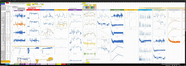
Avionics: GRT/Garmin/Dynon/AFS flight data analysis tool - Cloud-free and public domain!
Avionics: Adding voice alerts to GRT EFISs.

Avionics: Electronic ignition backup battery and controller.


Fuselage: Rudder and Brake Systems. Longer rudder cable links.


Most Recent Posts
25-Jul-25 - Modifications: Bigger oil cooler for IO-390-EXP119, try #3 (satisfactory performance).

10-Jun-25 - Modifications: Bigger oil cooler for IO-390-EXP119, try #2 (inadequate performance).

6-Jun-25 - Avionics: New indicator lights circuit board.

1-Jun-25 - Avionics: Oil quantity sensor installed.

20-May-25 - Avionics: B&C SF601 alternator replaces PlanePower AL12-EI60.

14-May-25 - Maintenance: Airflow Systems 2007X oil cooler failure in flight.

13-May-25 - Avionics: Connected right EFIS to backup battery and installed switch.

28-Dec-24 - Powerplant: Switched to automotive plugs and harnesses.


27-Oct-24 - Powerplant: Switched to dual SureFly electronic ignition.


10-Jun-24 - Modifications: Added tail cam for EFIS main screen.

27-Nov-24 - Mounted a tablet for free charts.

Pages Showing Modifications
- Aluminum vents
- Automotive plugs
- Aveo ZipTips Premiere 2 wing tips
- AveoMaxx Hercules 30 landing lights
- Backups
- Canopy lock
- Capacitive fuel probes
- Fabrication
- Install on original & replacement tanks
- Senders
- Carbon monoxide detector
- Dual pitots
- EXP119 engine converstion
- Footwell light
- Headset items
- Heated AOA/pitot probe
- Inflight toolbox
- Larger oil coolers
- Aero-Classics 8001643 (satisfactory)
- Aero-Classics 8001652 (inadequate)
- Airflow Systems 2007X (failed in flight)
- Locking fuel caps
- Low fuel level optical sensors
- Oil quantity sensor
- Painting
- Quarter-turn fasteners
- Rudder cable springs
- Rudder fairings
- SiriusXM satellite radio
- USB power for canopy cameras
- 14-May-25: Airflow Systems 2007X oil cooler failure in flight.
- 20-Feb-24: Crankshaft seal failure and replacement.
- 29-Nov-18: Fuel boost pump leak.
- 13-Aug-19: Starter failure #2. Replaced with different model: 149-NL.
- 27-May-19: Wheel fairing cracked.
- 12-Jan-19: Tension rod broke.
- 25-May-18: Rear window sealing.
- 20-May-18: Starter failure #1 (at 43 hours).
- 20-Nov-17: Propeller governor leak.
Pages by Plans Section
Click the headings to expand the lists.
Empennage Kit
- 06 Vertical Stabilizer (4)
- 07 Rudder (10)
- 07 Rudder Redo (1)
- 08 Horizontal Stabilizer (8)
- 08 Horizontal Stabilizer (Redo) (4)
- 09 Elevators (20)
- 10 Aft Fuselage (16)
- 11 Empennage Attach (2)
- 12 Empennage Fairings (4)
- Empennage (all) (68)
Wing Kit
- 13 Main Spar (5)
- 14 Ribs (12)
- 15 Rear Spar (4)
- 16 Top Skins (8)
- 17 Outboard Leading Edge (10)
- 18 Fuel Tanks (20)
- 18 Fuel Tanks (Redo) (12)
- 20 Bottom Skins (9)
- 21 Flaps (10)
- 22 Ailerons (10)
- 23 Aileron Actuation (5)
- 24 Wing Tips (9)
- Wings (all) (139)
Fuselage Kit
- 25 Forward Mid Fuselage Bulkheads (8)
- 26 Mid Fuselage Lower Structure (9)
- 27 Firewall (6)
- 28 Forward Fuselage Lower Structure (5)
- 29 Forward Mid Fuselage Side Structure (9)
- 30 Aft Fuselage Attachment (1)
- 31 Fuel System (1)
- 32 Baggage Area (2)
- 33 Rudder and Brake Systems (4)
- 34 Flap Actuation System (2)
- 35 Upper Forward Fuselage (4)
- 36 Aileron and Elevator Systems (3)
- 37 Roll Over Structure (1)
- Fuselage (all) (57)
Finishing Kit
FWF Kit
- 43 Engine Installation (3)
- 44 Spinner & Propeller (3)
- 47 Cowl Baffle (4)
- 48 Exhaust System (1)
- 49 Fuel and Oil System (2)
- Firewall Forward (all) (22)
Other Sections
Click each heading to expand the contents. Items in bold are of particular interest. Each subject's list is presented in reverse chronological order.
ADS-B (9)
- Mounted tablet for free charts via AvareX.
- SkyRadar DX removed in favor of a Stratux running Virtual Radar Server, #2.
- SkyRadar DX removed in favor of a Stratux running Virtual Radar Server.
- New GRT flight data analysis tool (for Garmin, Dynon and AFS too).
- Transponder upgrade.
- SkyRadar DX mount.
- 1090 MHz ADS-B in antenna installed
- Antennas mounted.
- Antennas purchased.
Antennas (5)
Autopilot (7)
Avionics (72)
- New indicator lights circuit board.
- Oil quantity sensor installed.
- B&C SF601 alternator replaces PlanePower AL12-EI60.
- Connected right EFIS to backup battery and installed switch.
- Replaced GRT HXr EFIS fan.
- Electronic ignition backup battery and controller.
- Mounted tablet for free charts via AvareX.
- Switched to dual SureFly electronic ignition.
- SkyRadar DX removed in favor of a Stratux running Virtual Radar Server, #2.
- Added tail cam for EFIS main screen.
- Added footwell light.
- Added SiriusXM.
- SkyRadar DX removed in favor of a Stratux running Virtual Radar Server.
- Backup alternator installed.
- Swapped out GTN-650 for GTN-650Xi.
- New GRT flight data analysis tool (for Garmin, Dynon and AFS too).
- Installed backup battery for Horis AI
- Installed alternator filter.
- Canopy cam mount change.
- New GRT and Garmin flight data logging analysis tool.
- Transponder upgrade.
- Redo of right side LEMO jack (plus filter capacitor).
- Screenshot pushbutton function.
- Installed CO Guardian carbon monoxide and pressure alarm.
- Minor change in electrical bus topology.
- Installed Kanardia Horis 57.
- Center console USB power socket change.
- Adding a lot more voice alerts on GRT EFISs!
- Canopy USB power change.
- GMA-240 replaced with GMA-245.
- New capacitive senders.
- Canopy cam(s)!
- Silencing the hash of a USB socket.
- Elevator trim wire wrap.
- Intercom output level for recording.
- Wing root wiring.
- Final panel image.
- The big master wiring post.
- Pitot static. Lines and wiring routed.
- Canopy harness, switch and fan wiring.
- SkyRadar DX mount.
- Magneto wiring.
- EGT and CHT wiring completed.
- GPS antenna shelf.
- Modified fuse block to support buses.
- MAP sensor connection
- Oil pressure switch
- Engine information system connection board
- Starter switch wires and installed.
- Antennas mounted.
- Nav/Strobe and landing/taxi lights circuit
- Indicator lights circuit.
- Lit up in airframe.
- LEMO connectors installed.
- Control column harness.
- AHRS Bracket.
- Panel assembly test fit.
- New sticks/control columns and grips.
- Bus topology resolved.
- Panel lit up and wiring tested.
- Garmin center stack trays fitted and EIS located.
- Magnetometer bracket fabricated and installed.
- ELT installed.
- Flap position sensor.
- Pitch servo installed.
- Bought a wire stripper.
- Purchased the glass of my glass cockpit.
- ELT purchased.
- Bought a crimper.
- Instrumentation fitment in panel.
- Panel design.
- Pitot-Static. Audible beeping tone with varying frequency.
Capacitive Fuel Probes (5)
- Fuel tanks redo. Capacitive plates installed. Tanks passed water test.
- Fuel tanks. Left tank capacitance probes and baffle install.
- Fuel tanks. Right tank capacitance probes and baffle install.
- Fuel tanks. Prepping for sealant, capacitive probes fabricated and locking caps.
- Fuel tanks. Capacitive fuel probes.
EAA Chapter 1000 Workbenches (4)
First Flight Preparation (7)
Fun Stuff (15)
- New GRT and Garmin flight data logging analysis tool.
- First "flight of two" air-to-air pics.
- First night flight.
- Quick performance numbers.
- My first landing.
- Progress pictures.
- Number of rivets in all kits.
- Number of rivets in wing, empennage, fuselage and finish plans.
- Bought my airplane a new house.
- Number of rivets in wing, empennage and fuselage plans.
- I made it to the mother ship! Lots of photos!
- Number of rivets in wing and empennage plans.
- Keychain.
- Motivational mousepad.
- A motivational poster.
Interior (11)
- Added footwell light.
- Added SiriusXM.
- Side panels.
- Poor man's seat warmers
- Headset hangers fabricated and installed.
- Seatbelt/Harness fitting fun.
- Koger sunshade installed.
- Canopy release handle painted.
- Seating, arm rests, lap and shoulder belts placed.
- Seats and interior items obtained.
- Purchased safety harnesses.
Lighting (12)
- Added footwell light.
- Aveo ZipTips Premiere 2 installed.
- First night flight.
- Landing light mounts fabricated.
- Nav/Strobe and landing/taxi lights circuit
- Nav-strobes wired and mounted.
- Landing lights. Wiring complete.
- Wing tips. Nav/strobe mounting holes cut.
- Landing lights ordered.
- Nav/strobe ordered.
- Leading edges. Landing light lenses cut.
- Landing light thoughts.
Low Fuel Level Optical Sensors (4)
Maintenance (24)
- Airflow Systems 2007X oil cooler failure in flight.
- Crankshaft seal failure and replacement.
- Third annual condition inspection.
- Fix cracks on wing tips.
- Complied with Slick SB-15A.
- Fuel boost pump leak.
- Second annual condition inspection.
- Steam gauge altimeter calibration
- Starter failure #2. Replaced with different model: 149-NL.
- Wheel fairing cracked.
- Tension rod broke.
- First annual condition inspection.
- SB 18-09-17 Aft bottom skin cracking.
- Changed static ports and associated plumbing
- Wing jack.
- My inflight toolbox.
- Starter failure at 43 hours.
- Cowl and NACA plugs.
- Oil change 2.
- Elevator trim wire wrap.
- Replacing roll servo shear screw and re-rigging.
- First oil change.
- Prop greasing.
- Propeller governor leak.
Modifications (31)
- Bigger oil cooler for IO-390-EXP119, try #3.
- Bigger oil cooler for IO-390-EXP119, try #2.
- Added tail cam for EFIS main screen.
- Bigger oil cooler for IO-390-EXP119, try #1 (failed in flight).
- Added footwell light.
- IO-390-A3B6 to -C3B6 (-EXP119) Conversion.
- Backup alternator installed.
- Aveo ZipTips Premiere 2 installed.
- Changed oil cooler SCAT to 5"
- Filled hole for stall vane.
- Increasing roll servo leverage.
- Canopy lock.
- New capacitive senders.
- Rear window sealing.
- Oil pan heater.
- Rudder pedal springs.
- Headset hangers fabricated and installed.
- Rudder fairings installed.
- Rudder and brake systems. Rudder pedals.
- Fuel tanks redo. Capacitive plates installed. Tanks passed water test.
- Heated AOA/pitot wiring complete.
- Left tank capacitance probes and baffle install.
- Right tank capacitance probes and baffle install.
- Dual pitot plumbing completed.
- Pitot hole made.
- AOA pitot mount.
- Prepping for sealant, capacitive probes fabricated and locking caps.
- Dynon AOA pitot.
- Fuel tanks. Match drilled, countersunk and low level fuel sensor.
- Capacitive fuel probes.
- Stall warner assembled and landing light cavity painted.
Moving to Hangar (2)
Operational (8)
Painting (10)
- Bottom cowl paint prep.
- Vinyl wrap experiment II - canopy fairing.
- Top cowl paint prep.
- Vinyl wrap experiment.
- Canopy fairing paint prep.
- Fairings preperation.
- Interior painting completed.
- Interior paint planning.
- Rudder and brake systems. Rudder pedals.
- Leading edges. Stall warner assembled and landing light cavity painted.
Panel (15)
- New indicator lights circuit board.
- Connected right EFIS to backup battery and installed switch.
- Transponder upgrade.
- Final panel image.
- Airspeed indicator purchased.
- Nav/Strobe and landing/taxi lights circuit
- Indicator lights circuit.
- Panel: Lit up in airframe.
- Panel assembly test fit.
- Panel lit up and wiring tested.
- Garmin center stack trays fitted and EIS located.
- Panel cut.
- Purchased the glass of my glass cockpit.
- Instrumentation fitment in panel.
- Panel design.
Pitot-Static (12)
- Steam gauge altimeter calibration
- Changed static ports and associated plumbing
- Lines and wiring routed.
- Pitot-static-AOA system routed in airframe
- Audible beeping tone with varying frequency.
- Mast powder coated.
- AOA/pitot doubler plate riveted in.
- Heated AOA/pitot wiring complete.
- Dual pitot plumbing completed.
- Pitot hole made.
- AOA pitot mount.
- Dynon AOA pitot.
Powerplant (14)
- Bigger oil cooler for IO-390-EXP119, try #3.
- Bigger oil cooler for IO-390-EXP119, try #2.
- Switched to automotive plugs and harnesses.
- Electronic ignition backup battery and controller.
- Switched to dual SureFly electronic ignition.
- Bigger oil cooler for IO-390-EXP119, try #1 (failed in flight).
- Crankshaft seal failure and replacement.
- IO-390-A3B6 to -C3B6 (-EXP119) Conversion.
- Complied with Slick SB-15A.
- Engine installation.
- Firewall forward kit ordered.
- Engine delivered.
- Propeller delivered.
- Propeller and engine ordered.
Practice Projects (5)
Priming (24)
- Fuselage: Multiple sections. Priming.
- Fuselage: Multiple sections. Priming.
- Fuselage: Multiple sections. Priming.
- Fuselage: Forward mid and lower structures. Priming.
- Fuselage: Firewall. Priming.
- Fuselage: Mid Fuselage Lower Structure. Priming.
- Fuselage: Forward Mid Fuselage Bulkheads. Priming.
- Wings: Fuel tanks redo. Primed their exteriors.
- Empennage: Aft fuselage. Final priming.
- Empennage: Aft fuselage. Priming.
- Empennage: Elevators. Left elevator parts primed.
- Empennage: Elevators. Right elevator parts primed.
- Empennage: Priming. Rudder and horizontal stabilizer.
- Empennage: Rudder, vertical and horizontal stabilizers priming.
- Wings: Aileron actuation. Priming and flash rust.
- Wings: Ailerons. Prime time.
- Wings: Flaps. Parts primed.
- Wings: Bottom skins. Prepping skins and priming gap fairings.
- Wings: Fuel tanks. Parts deburred and primed.
- Wings: Leading edges. Priming.
- Wings: Top skins. Primed.
- Wings: Rear spar. Priming rear spar.
- Wings: Ribs. Prime rib.
- Wings: Main spar. Countersinking and spot priming.
Setup (3)
Shop (25)
- Shop/Wiring: Bought a wire stripper.
- Shop/Wiring. Bought a crimper.
- Trailing edge squeezer dies.
- Bought a Semco sealant gun.
- Belt sander purchased.
- Rivet shaver bliss.
- Rivet shaver experience.
- Wings: Top skins. Prepping for riveting.
- Wings: Rear spar. Attached.
- New drill press.
- Deburring ribs made easy!
- Setup and Project 2.
- More tool updates.
- Tools, it never ends.
- Toolbox kit complete.
- Pneumatic cleco tool.
- Dimpler platforms.
- Table 4.
- Table 3.
- Table 2.
- Time for a miter saw.
- First table construction.
- Workshop prep.
- Computer setup.
- Tools and more tools!
Technical Counselor Visit (5)
Wiring (12)
- Wing root wiring.
- The big master wiring post.
- Canopy harness, switch and fan wiring.
- EGT and CHT wiring completed.
- Modified fuse block to support buses.
- Aiframe Harnesses
- Bus topology resolved.
- Panel lit up and wiring tested.
- Bought a wire stripper.
- Bought a crimper.
- Landing lights. Wiring complete.
- Autopilot wiring.
Work Graph as of 4-Sep-17

Cumulative hours on the build vs. time.
Cost as of 1-Nov-17
Hover your mouse over most categories for itemization.| Category | Amount |
|---|---|
| Avionics and Panel | $38,805.90 |
| Antennas | $1,086.33 |
| CPU for Shop | $531.31 |
| Engine and Prop | $42,145.00 |
| Fuel Tanks Redo | $1,537.51 |
| Fuselage Bulkheads | $1,315.77 |
| Interior | $2,477.41 |
| Kits from Van's | $41,750.13 |
| Lighting | $3,022.54 |
| Maintenance | $775.77 |
| Modifications | $2,303.66 |
| Other | $3,391.36 |
| Paint and Primer | $1,203.96 |
| Replacement Parts | $2,123.02 |
| Rudder Redo | $493.52 |
| Tools and Shop | $12,773.35 |
Number of Rivets
| Empennage | 4,446 |
| Wings | 8,276 |
| Fuselage | 6,250 |
| Finish | 1,265 |
| FWF | 234 |
| Optional | 20 |
Total: 20,499